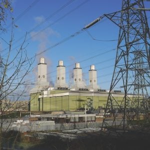
The carbon dioxide emissions produced by power generation account for more than 40% of total world CO2 emissions but due to their capacity to adapt to fluctuations in grid demand, gas fuelled power plants are projected to continue to play a significant role in power generation, with gas turbine based power plants being extensively used for the purpose of mitigating grid volatility and meeting fluctuating power demand, as well as power generation per se.
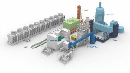
GE Vernova is working with power plant operators and partners to create strategies for reducing the CO2 intensity (amount of CO2 emitted per unit of electricity generated) of gas turbine based power plants. This involves implementing measures such as enhancing plant efficiency, reducing carbon content in fuel by using low-carbon fuel alternatives like hydrogen, and adopting carbon capture and storage/utilisation technologies (Figure 1).
GE Vernova strengthens the commercial viability and visibility of carbon capture plant integration with combined cycle power plants through the implementation of strategies such as steam integration, exhaust gas recirculation, gas turbine upgrades, and advanced control systems.
Steam integration is the extraction of steam from the combined cycle steam turbine crossover rather than using an auxiliary boiler (the ‘bolt-on’ solution). Steam integration not only improves site fuel consumption but also lowers the carbon capture plant’s capex and footprint by reducing CO2 site emissions.
Exhaust gas recirculation sends a portion of the stack flue gas to the gas turbine, hence elevating the flue CO2 concentration and reducing the volume of flue gas directed to the carbon capture plant.
The CO2 capture rate is directly influenced by the CO2 partial pressure, which is directly proportional to the concentration of CO2 in the flue gas. The cost of CO2 capture is influenced by the partial pressure, since it directly impacts the dimensions of the equipment, power consumption, and the selection of the capture method.
The CO2 concentrations in exhaust gas from different sources show significant variations, which directly affect the performance, design, and selection of capture plant technologies, as well as the capital expenditure and operating expenditure.
The exhaust gas from large land-based gas turbines contains 3-4.5% mol CO2 at near-atmospheric pressure, depending on the gas turbine frame (E, F, or HA class).
When compared to sources that have a high concentration of CO2, carbon capture is more challenging and requires more energy to remove the CO2 from sources that have a low concentration of CO2, such as natural gas fuelled combined cycle power plants. Exhaust gas recirculation elevates the CO2 concentration in gas turbine exhaust to approximately 6-7% mol, dependent upon the exhaust gas recirculation ratio. Exhaust gas recirculation enhances the performance of carbon capture plants, lowers overall capital expenditure, and mitigates solvent losses by lowering the degradation rate.
Amine based carbon capture
Amine based solvent post-combustion carbon capture technology (Figure 2) depends on the chemical properties of the amine–CO2-H2O system and the ability of amine solution to trap CO2 at low temperatures and release it at higher temperatures. Carbon dioxide and water react to produce carbonic acid, which subsequently undergoes a reaction with an amine solution in the absorption column.
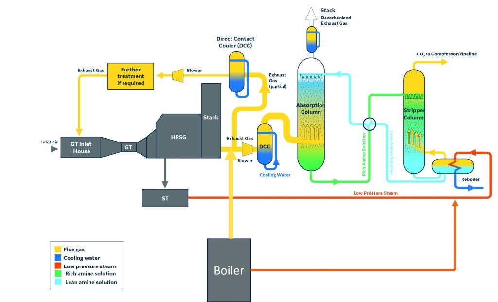
This reaction results in the creation of a solution that absorbs carbon dioxide from
the gaseous stream.
The flue gas is diverted from the existing HRSG plant stack in a way that does not impact the operation of the power plant. Shutoff dampers are installed to isolate the ducts from the main HRSG stacks. During normal operation, the shutdown dampers of the capture plant will be fully open. The flue gas is cooled by introducing water into the top of the DCC (direct contact cooler), with gas entering from the bottom section of the DCC. The DCC operates as a quenching tower, where water undergoes condensation from the flue gas and gets driven out from the loop as water blowdown. The cooled and cleaned flue gas is introduced into the CO2 absorber in a temperature range of 40°C to 50°C and at normal atmospheric pressure. Variable-frequency blowers are employed to move the flue gases from the DCC to the absorber and to overcome the drop in pressure in the main ducts and the absorber column.
The CO2 absorber is constructed as a packed tower, with a design that ensures the flue gas is equally distributed throughout the column. High-performance packing is installed to ensure efficient mass transfer and to reduce the column diameter and pressure drop. The CO2 in the flue gas is chemically absorbed as it moves upwards in a counter-current direction with the spraying CO2-lean amine solution that is flowing from the upper part of the absorber. The exiting solution at the bottom of the absorber, the CO2-rich amine solution, is subsequently circulated via a cross-flow heat exchanger and heated to a higher temperature by the lean solution that is being returned from the amine regenerator column.The CO2-rich amine solution is pumped through the lean/rich amine cross heat exchanger and heated before being sent to the top of the regeneration column. The regenerator column is a distillation column with packing. There, the rich solution flows down the column counter-current to steam generated by boiling a portion of the lean solution that exits the bottom of the regeneration column. The stripper receives heat through the stripper reboiler which is situated at the bottom of the stripper. The reboiler is a kettle heat exchanger where steam flows through the tube bundle and exits as condensate and the solvent is heated against the steam. The lean solution in the amine regenerator is fed back to the absorber via the lean/rich amine cross heat exchanger. The heated lean solution is cooled, and the heat recovered heats the rich CO2 solution from the absorber. The generated gas at the top of the stripper, consisting primarily of carbon dioxide and water vapour, is directed through a series of compressors, coolers, and dryers to eliminate the water vapour from the CO2 and increase its pressure to required pressure at the storage location.
Cost savings from steam integration
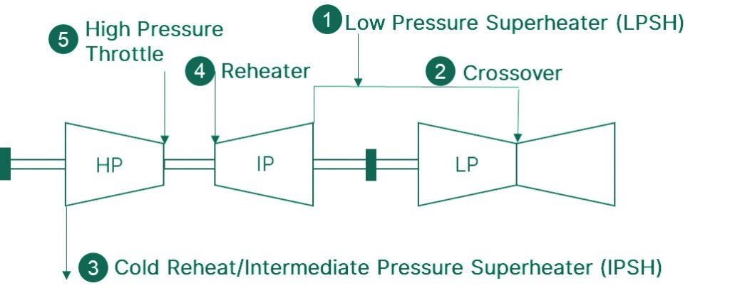
Consider a (1×1) HA-class gas turbine natural gas combined cycle plant with a post-combustion carbon capture plant. The steam turbine is configured with an IP-LP crossover for steam extraction (see Figure 3) while the heat recovery steam generator consists of a 3-pressure level HRSG with reheat. The carbon capture plant is an aqueous amine-based capture system.
Two sources of steam can be used to power the reboiler: an external auxiliary boiler (bolt-on solution) or the existing combined cycle plant’s steam turbine. The required steam quality for a combined cycle power plant depends on the reboiler temperature, which is determined by the selected solvent/solvent mixture.
The bolt-on solution is a straightforward way of generating steam with least to no integration with the combined cycle power plant. The bolt-on approach involves installing an external auxiliary boiler to provide the necessary steam to the reboiler. To achieve the desired capture rate for the site, it is necessary to take account of the CO2 emissions generated by the auxiliary boiler. Thus, the carbon dioxide capture plant will also receive the exhaust gases from the auxiliary boiler. To deal with these CO2 emissions generated by the auxiliary boiler, both the carbon capture plant and the auxiliary boiler must be larger.
In contrast, the steam integration solution involves the extraction of steam from the combined cycle plant. The choice of steam extraction point in the combined cycle power plant is based on the steam temperature and quality needed in the reboiler. Generally, the steam quality at the reboiler interface is around 4-6 bar saturated. This implies that the intermediate pressure (IP) and low pressure (LP) crossover is the most favoured location for steam extraction. A throttle valve allows steam to be drawn from the IP/LP turbine crossover, taking account of the pressure loss in the steam pipelines and the mean temperature differential in the reboiler. An attemperator is required to manage the temperature of the steam draw by spraying condensate to keep the temperature just above saturation when it enters the reboiler.
When compared to bolt-on solutions, the steam integration solution offers significant carbon capture cost savings. There is no need for an auxiliary boiler because the steam to the carbon dioxide capture plant is extracted from the steam turbine IP/LP crossover, as already noted.
The bolt-on solution increases the size of the CO2 capture plant needed and the total amount of fuel consumed on site by installing an additional external auxiliary boiler to supply steam to the capture plant. The natural gas fuelled combined cycle power plant and the auxiliary boiler both produce carbon dioxide emissions, which the capture plant is designed to capture.
As noted, this will lead to an increase in the capture plant’s size, power consumption, and footprint. The bolt-on solution increases the overall amount of carbon dioxide emissions sent to the capture plant by up to 30%, assuming a 95% capture rate for the capture plant.
Implementing a bolt-on solution reduces the natural gas fuelled combined cycle system’s net efficiency by about 20% when compared with the NGCC base case without CO2 capture. When using the steam integration option, however, the net NGCC efficiency decreases by approximately 8%. The bolt-on solution’s NGCC output drop is roughly 6%, whereas the steam integration solution’s is 12%.
It is also possible to employ an optimised combination of steam integration and auxiliary boiler to achieve the required balance of capex, opex and operability needed for a given plant.
Why exhaust gas recirculation?
With exhaust gas recirculation (EGR), a portion of the HRSG exhaust flue gas flow is reintroduced into the inlet of the gas turbine after appropriate cleaning and conditioning.
EGR offers two key advantages. First, the flue gas directed to the carbon dioxide capture plant is reduced proportionally with the EGR rate. This reduction in mass flow to the capture plant decreases the size of major capture plant components, including the direct contact cooler and the absorber, leading to a decrease in both footprint and capex of the capture plant. Second, since EGR increases the concentration of CO2 in the exhaust gases, resulting in a higher CO2 partial pressure in the flue gas, the driving force in the separation process is enhanced. In other words, EGR enables the capture plant to capture the same amount of CO2 from exhaust gases while treating a smaller volume of flue gases. This leads to a reduction in the capture plant footprint, capex, and opex. Furthermore, EGR helps mitigate amine degradation linked to O2 in the exhaust gas, with a consequent decrease in amine make-up flow, thereby improving the overall opex of the CO2 capture plant.
Combustion dynamics, emissions, and the O2 concentration at the gas turbine combustor input, limit the EGR ratio. For example, at a 30% EGR ratio, CO2 concentrations in exhaust gases increase by nearly 40%. However, increasing the EGR ratio to 30% lowers the O2 concentration in the combustor by nearly 20%.
It is essential to effectively clean the EGR flue gases before reintroducing them into the gas turbine inlet, to remove NOX, SOx, and particulate matter. The EGR cooling loop with an enhanced direct contact cooler is intended to provide high levels of EGR flow scrubbing and cooling to ensure continuing gas turbine operation. The EGR DCC cooler is designed as a packed column, with cooling water recirculated to the top and sprayed in a counter-current way. The EGR gas flow is cooled down as it encounters the spraying water. The EGR cooling temperature is determined by evaluating gas turbine performance and the cost of the EGR cooler. Depending on the site location and water availability, the EGR cooling loop can be equipped with a water, air, or hybrid cooling system.
The CO2 capture equipment is divided into four primary categories: pre-scrubber or DCC; absorption system; stripper system; and CO2 compression train. Flue gas cleaning and capturing systems, including absorption and pre-scrubber systems, account for roughly 60% of overall capture plant equipment costs. The stripper system contributes around 24% of the entire capture plant cost, while the CO2 compression train accounts for roughly 19%, see Figure 4.
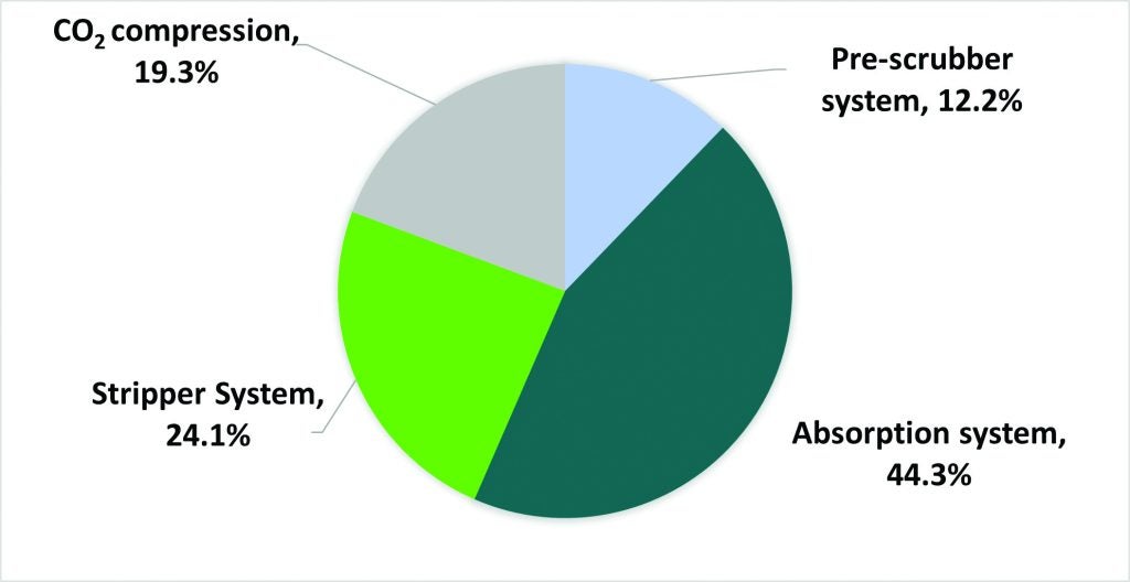
It is important to keep in mind that this cost breakdown may vary depending on the specific configuration of the capture plant, but the absorption system consistently remains the most significant equipment cost in the capture plant.
This emphasises the significance of cost reduction in the absorption system in order to reduce the total capture plant capex. Absorbers are typically dimensioned according to the volumetric flow of flue gases, with the absorber diameter selected to ensure a safe flooding velocity. EGR reduces the quantity of flue gas that is directed to the absorber by recirculating a portion of it back to the gas turbine inlet and increasing the CO2 concentration in the flue gas directed to the CO2 capture plant.
When 30% of the exhaust gas is recirculated, the cost of the pre-scrubber and absorption system equipment drops by 20-25% due to the smaller column diameter. The cost savings vary depending on the column configuration, the number of columns, and number of capture plant trains. The total cost of the CO2 capture plant, which includes the absorption system, regeneration system, and CO2 compression train, might be reduced by about 15% when compared to the non-EGR scenario. The total cost savings for a natural gas fuelled combined cycle power plant with CO2 capture system including EGR equipment and required modifications, range between 5 and 8%, see Figure 5.
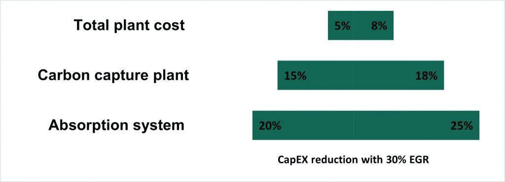
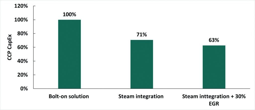
Figure 6 shows the decrease in capex for the capture plant when steam integration and a 30% EGR are implemented, in comparison to a bolt-on solution. Steam integration reduces the capture plant capex by up to 30%, with an additional 7% reduction achieved by implementing a 30% EGR. These estimates will vary depending on the actual plant specification parameters, the type of capture solvent, and site-specific constraints.
Gas turbine upgrade and advanced control systems
The operation of a carbon capture plant requires a constant supply of steam for the regeneration of CO2 and provision of electrical power for the operation of the CO2 compression train and the balance of plant in the carbon capture process. Typically, a natural gas fuelled combined cycle power plant would experience a decrease in both net electricity export and efficiency because of the extraction of steam and supply of electrical power. A gas turbine, steam turbine, HRSG and plant upgrade is an efficient and cost-effective method for recovering a significant portion, if not the majority, of the lost net power production. The upgrading required for a gas turbine differs depending on the gas turbine frame and configuration and must be assessed individually for each specific scenario. An advanced gas path (AGP) is a highly effective modification for gas turbines that can increase their power output. An advanced control system is necessary to enable the effective operation of the combined cycle power plant and capture plant under various operating conditions, including base load, part load, start up, shutdown, and upset scenarios.
Barry feed study
The US Department of Energy’s Office of Fossil Energy and Carbon Management has released the official findings of a GE Vernova led front-end engineering design (FEED) study Retrofittable advanced combined cycle integration for flexible decarbonized generation.
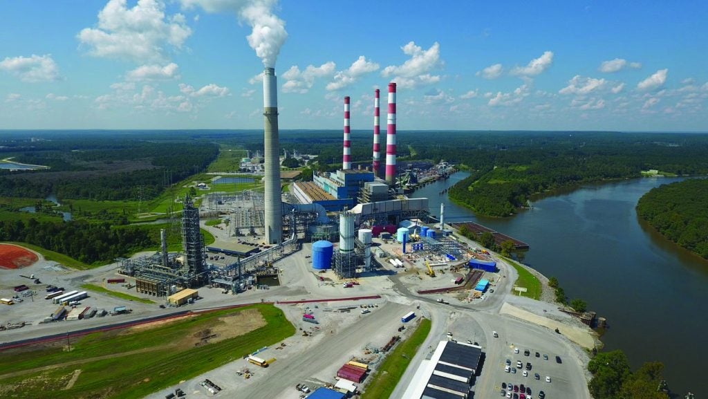
The study focused on retrofitting Southern Company subsidiary Alabama Power’s James M. Barry unit 6 combined cycle plant (located in Bucks, Alabama) with technology capable of capturing up to 95% of the plant’s CO2 emissions. See Figures 7 and 8.
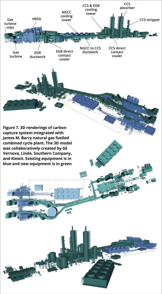
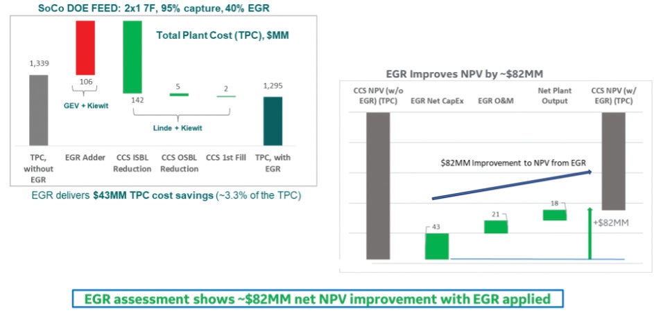
In the study, measures and technologies considered demonstrated the use of NGCC power plant steam in the carbon capture system, implementation of gas turbine upgrades, installation of NGCC and carbon capture control systems, and employment of GE Vernova’s EGR system. Taken together, these steps would help reduce the size and the costs of the carbon capture system by potentially halving the number of absorber towers, improving the efficiency and flexibility of the plant and increasing its power output. The EGR resulted in improved total installed cost ($43 million), reduced operations and maintenance costs ($21 million) driven by the reduced CCS oxidation driven solvent degradation and improved net plant output and heat rate ($18 million) due to the reduced steam extraction for CCS reboiler because of the increased CCS inlet CO2 concentration. See Figure 9.
The capture concept considered in the FEED study was Linde’s Gen 2 technology, based on BASF’s OASE® blue gas treatment system.
The study was carried out by GE Vernova in collaboration with Southern Company, Linde, BASF and Kiewit.