
The basic gas turbine cycle and construction have not changed in the eighty years since the Jumo-004 turbojet engine entered wartime service in Germany in 1944. The operation of a gas turbine is described by the ideal “air-standard” Brayton or Joule cycle comprising four basic processes: isentropic compression; constant pressure heat addition; isentropic expansion; and constant pressure heat rejection. The ideal cycle describes a heat engine, which is a poor approximation of the ultimate heat engine operating in a Carnot cycle. (In the latter, heat addition and rejection processes are isothermal.) The actual machine, strictly speaking, is not a heat engine; it is an “energy conversion” device and does not operate in a thermodynamic cycle. This is why a gas turbine power plant is commonly referred to as an “open cycle” – an oxymoron – power plant in the literature. (The exception is the “closed cycle” – a tautology – gas turbine, which has been tried in the past with limited commercial success.)
The net shaft power output of a gas turbine is determined by the difference between the power consumed by the compressor and the power generated by the expander (ie, the turbine). In a modern machine, roughly one half of the expansion power is consumed by the compressor. This is the reason why turbine inlet temperature is the key knob to make the ratio more favourable, ie, increase the net power output. The improvement, however, comes at the expense of increased fuel burn in the combustor and adversely affects the thermal efficiency. The balancing act involves an increase in the cycle (ie, compressor) pressure ratio to increase the temperature of the air entering the combustor, which is counter-productive because it increases the power consumption of the compressor. To make a long story short, this balancing act results in a symbiotic relationship between the cycle/compressor ratio (PR) and the turbine inlet temperature (TIT), which resulted
in a concomitant rise in both over the last four decades. From the early E class with 1300°C–12:1 (TIT–PR) combo to the F class with 1400°C–15:1 and, finally, to the present-day advanced class gas turbines with close to 1700°C and 25:1, with thermal efficiencies of 43-44% (ISO baseload on a lower heating value (LHV) basis). In a combined cycle configuration, today’s state-of-the-art is around 64% LHV (ISO baseload) with the advanced class gas turbines.
Further increase in thermal efficiency without a change to the underlying Brayton cycle has already become an endeavour of diminishing returns. Emerging technologies such as additive manufacturing, exotic hot gas path materials, and 3D computational design platforms can (and do) result in incremental improvements
but they are unlikely to bring the technology to the next level on their own. (70% net LHV efficiency is an oft-cited target.) One such change, at an ideal cycle level, is a switch from constant pressure (isobaric) heat addition to constant volume (isochoric) heat addition. As can be easily recognised from the ideal gas equation of state, pv = RT, the advantage of this cycle mod is that an increase in working fluid temperature is accompanied by a commensurate increase in pressure. In other words, a portion of cycle pressure rise can be transferred from the power consuming mechanical compression to the heat addition process (ie, thermal compression). In fact, there is an ideal cycle like that in the literature: the Atkinson cycle (frequently referred to as the Humphrey cycle in detonation combustion circles).
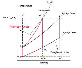
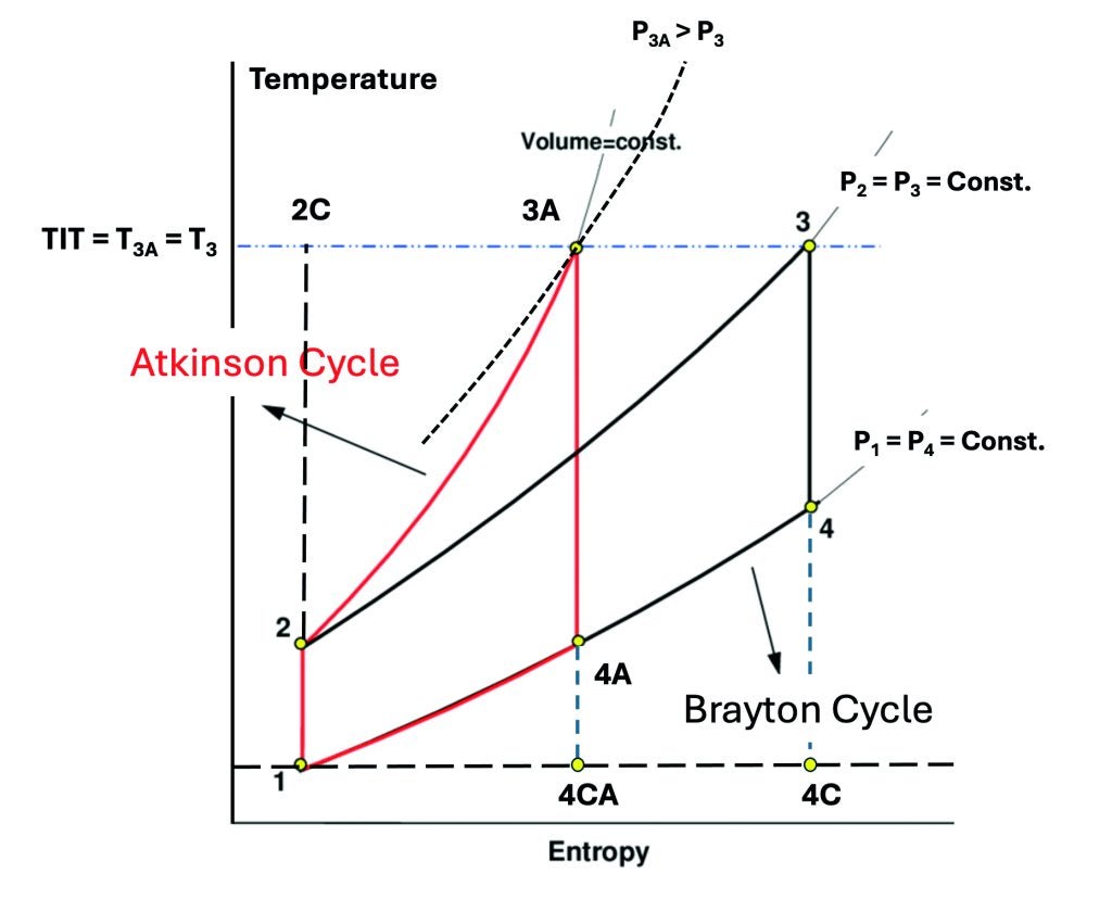
A graphical comparison of air-standard (ideal) Atkinson and Brayton cycles with the same cycle maximum temperature (ie, T3, the ideal cycle proxy for TIT) is provided in Figure 1. The cycles are depicted on a temperature-entropy (T–s) diagram, which is the most convenient way to visually describe the cycle thermodynamics. To be precise, there are four ideal cycles shown in Figure 1, namely:
- Two Carnot cycles, {1–2C–3–4C–1} and {1–2C–3A–4CA–1}, which represent the theoretical maximum efficiency set by the second law of thermodynamics, ie, 1 – T1/T3.
- The Brayton cycle {1–2–3–4–1}, a poor substitute for the Carnot cycle, whose efficiency is a function of the cycle pressure ratio, PR = P2/P1, only.
- The Atkinson cycle, another Carnot substitute, where the isochoric heat addition process further increases the cycle pressure ratio. Note that the Atkinson cycle efficiency is a function of the pre-compression ratio, r = v1/v2, and TIT, which sets the thermal pressure ratio rp = P3A/ P2 (= T3A/T2), as mentioned above.
Why the Atkinson cycle is better than the Brayton cycle may not be that obvious to the naked eye. Let us use some numbers for illustration and assume that the Brayton cycle PR = 15:1 (typical F class). The cycle efficiency is 53.9%. For TIT = T3 = 1400°C, the Carnot efficiency is 82.8%, which leads to a “cycle factor” of 53.9/82.8 = 0.65, which is a measure of the “goodness” of the cycle. Changing the isobaric heat addition process {2→3} to isochoric {2→3A}, the cycle PR increases to ~40:1 (same TIT). The Atkinson cycle efficiency is 60.7% for a cycle factor of 60.7/82.8 = 0.73, ie, significantly better than its Brayton cousin.
This finding is not entirely unexpected, of course. The underlying thermodynamic driver is the same as those in action in aeroderivative gas turbines (high cycle PR) and gas-fired “diesel” (a reference to the Diesel cycle) or reciprocating (“recip”) engines with explosion combustion in the cylinder. State-of-the-art versions of the latter are pushing 50% in thermal efficiency, cf. 43-44% for the advanced class gas turbines. (In passing, controlled explosion inside the engine cylinder is not detonation, which can indeed happen but leads to the undesirable and damaging phenomenon commonly known as knocking.) The practical or hardware counterpart of ideal constant volume heat addition is pressure gain combustion (PGC). On paper, using ideal thermodynamic relationships as described above, the concept is unassailable. Translation of it to actual hardware in an intermittent flow device such as a recip engine with in-cylinder explosion combustion has been successfully done with proven commercial success. As an interesting historical note, a PGC gas turbine was invented in Germany by Holzwarth, whom Stodola credited for “having built the first economically practical gas turbine” (around the start of the twentieth century). Holzwarth’s fin de siècle intermittent flow turbine, in its latest installed version in Mannheim, Germany (1920), with a valve-controlled and water-cooled combustion chamber and operating in an expansion-scavenging-precompression-explosion cycle, ultimately proved too complicated and expensive to be a viable product.
It is easy to see why PGC has not been successfully integrated into a modern gas turbine, which is a steady flow device. From the fundamental fluid mechanics, it is known that a steady flow process with an increase in pressure is an impossibility. The only exception is a standing shock wave, which is idealised as a discontinuity in the flow regime, across which the fluid speed decreases from supersonic to subsonic with accompanying rise in pressure and temperature. This, of course, is what happens at the inlet of a ramjet engine flying at supersonic speeds. The principle has been utilized in practice in the Pratt & Whitney J58 quasi “turboramjet” engines (two of them) deployed in SR-71 Blackbird aircraft. Alas, making it an integral part of the engine configuration to facilitate detonation combustion in a seamless process is an altogether different matter.
The physical mechanism to achieve PGC in a steady flow device such as a gas turbine is detonation combustion, which is significantly different from its conventional counterpart, deflagration combustion. Germans had already recognised this in 1940s. In particular, work done by a team led by Dr R. Focke in BMW looked at an engine design, IPTL 8000, with an estimated performance of 800 km/h airspeed at sea level (8000 BHP) with an assumed propulsive efficiency of ƞp = 80%, air consumption of 62 lb/s and SFC (specific fuel consumption) of 0.521 lb/BHP-h (about 26%, cf. barely 14% for the Jumo-004 turbojet engine that powered Me 262 jet fighter). For details of the experimental “detonation combustion” chamber, see the monograph by Kollmann, Douglas, and Gülen.[1] Seventy years later, GE, in co-operation with NASA, also tested a multi-tube pulse(d) detonation combustor (PDC) and turbine hybrid system. Eight PDC tubes were arranged in a manner similar to IPTL 8000 (like a Gatling gun) “firing” into a single-stage axial turbine (1000 HP nominal rating at 25 000 RPM). According to GE, the system was operated at frequencies up to 30 Hz (per tube) in different firing patterns using stoichiometric ethylene–air mixtures to achieve 750 HP at 22 000 RPM.
Even with a flight prototype demonstration powered by a pulse(d) detonation engine (PDE), namely the Long-EZ aircraft in 2008, the PDC concept, with its myriad practical difficulties was eventually dropped in favour of rotating detonation combustion (RDC) and the rotating detonation engine (RDE). In simple terms, RDC avoids the valving problems associated with PDC due to its much higher frequency of “firing”, 1-10 kHz (ie, up to 10 000 times per second), vis-à-vis PDC with around 100-200 Hz or less. Thus, the extremely rapid nature of RDC ensures a much better approximation of a smooth, continuous combustion process, which is more suitable to aerospace propulsion applications in comparison to the intermittent nature of PDC (eg, less vibration, one ignition at start versus ignition at each pulse, etc).
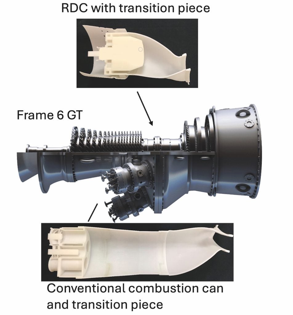
While the main interest in RDC/RDE is for aerospace propulsion, specifically for hypersonic flight applications, there is also the possibility of its application to a land-based gas turbine for mechanical shaft power and electric power generation. In 2022, GE Research, in collaboration with GE Aerospace and several academic institutions, received funding from the US DOE to design, fabricate, and demonstrate operation of an RDC at F class gas turbine conditions (up to 800°F, 250 psia) while integrated with upstream and downstream turbomachinery components. According to the DOE, the aim is to advance technical understanding of the application of an RDE in a hybrid gas turbine cycle for the purpose of land-based power generation (including RDC with hydrogen fuel). Four-year project deliverables include low-loss RDC design for turbine integration, experimental demonstration of compressor and turbine integration, and RDC-integrated GT performance estimate. (Preliminary results of the combustor architecture study for a Frame 6FA are shown in Figure 2.)
Reasonable performance improvement expectations from an RDC-equipped gas turbine are about 5-7 percentage points for simple cycle and about 2-3 percentage points for combined cycle.[2]
It should be noted that, increased cycle pressure ratio at the same turbine inlet temperature reduces the bottoming cycle work potential, eg, compare the area {1–4A–4CA–1} with the area {1–4–4C–1} in Figure 1. The quick remedy is an increase in T3 but that would be equally advantageous for the Brayton cycle as well. Thus, the final TIT-PR selection for an RDC gas turbine is critical to fulfilling the ideal cycle potential of pressure gain combustion via detonation vis-à-vis the deflagration version. Comparisons with the conventional technology must be made on a truly “apples with apples” basis. Unfortunately, most PGC performance advantage claims in the literature are based on faulty fundamental thermodynamic analysis and misleading assumptions. In any event, the technology is in its infancy with a lot of R&D work remaining to fully understand the physical drivers in action (eg, why the wave rotation, why in one direction and not the other, why not just exit the “combustor” – just an annulus – flaming out, and so on). This could easily take another decade before the technology reaches a high level of technical readiness.
[1] Karl Kollmann, Calum Douglas, S. Can Gülen, Turbo/supercharger compressors and turbines for aircraft propulsion in WWII: theory, history and practice – guidance from the past for modern engineers and students, ASME Press, ISBN 978-0791884676, August 2021.
[2] S. Can Gülen, Pressure gain combustion advantage in land-based electric power generation, GPPF2017-0006, 1st Global Power and Propulsion Forum, GPPF 2017, 16-18 Jan 2017, Zürich, Switzerland.