GAS TURBINE O&M REVIEW
Axial flow compressor issues
1 December 2008Following on from his previous article in this gas turbine O&M series (November 2007), Meherwan Boyce (of the Boyce Consultancy Group, Houston, TX, USA) brings his 45 years of turbomachinery experience to bear on problem areas in the axial flow compressors of advanced gas turbines.
Modern large combined cycle power plants use advanced gas turbines that were developed for high efficiency and base load operation (1 start in every 1000 hours of operation). The reality over the past ten years has been different, with most combined cycle power plants operating under cyclic conditions where the units are turned on and off on a weekly and in many cases a daily basis. Further more the load at off prime time can be as low as 40-50% of the baseload on a daily basis. These changes in operation mode in many cases require more frequent maintenance and inspection.
The gas turbines used in large combined cycle power plants operate at very high pressure ratios, and turbine firing temperatures. The compressor pressure ratio is high which leads to a very narrow operation margin, thus making the turbine very susceptible to compressor fouling, and the very high compressor exit temperatures mean cooling is required before the air can be used for cooling turbine blades. The high efficiency air filter, which is placed in front of the axial flow compressor, also results in major deterioration of the performance of the turbine if not maintained properly. Many units also use evaporative cooling or fogging. These systems should be very carefully designed as they can result in loss of blades in the first couple of rows of the compressor due to large droplets impacting the blades. Most units which use evaporative cooling suffer from, at the minimum, leading edge erosion, which in most cases does not lead to blade failure.
The design of the industrial gas turbine has in the past emphasised long life and this conservative approach has resulted in the industrial gas turbine in many aspects giving up high performance in favour of rugged operation. However, the new industrial gas turbines incorporate features from aeroderivative machines, with increased blade loading on axial flow compressors and high pressure ratios.
Axial flow compressor features
The compressor consumes over 55-60% of the total power generated by the gas turbine. Therefore, compressor problems, such as fouling, can have a significant impact on turbine performance. Pressure ratios have increased from about 7:1 in the 1950s to 35:1 in the 2000s. This increase in compressor pressure ratio decreases the operating range of the compressor. The safe operating range of the compressor, at constant speed, stretches from the surge line at the low flow end of the compressor constant speed line to the choke point at the high flow end. This operational range difference can be about 2.5-3.5% of the design flow. The lower pressure compressor has a larger operational range than the higher pressure compressor. Therefore, the higher pressure ratio compressors are more susceptible to fouling, and this can result in surge problems or blade excitation problems, which can lead to blade failures. A drop in pressure ratio at the turbine inlet due to filter fouling results in a substantial loss in turbine overall efficiency and power produced.
Table 1 shows the effect of changes in various parameters on output and heat rate. These were selected because they are the most common changes that occur in a system in the field. It must be remembered that these are just approximations and will vary for individual power plants.
The axial flow compressor with high pressure ratios in the advanced gas turbine is a multistage compressor (17-22 stages). The more stages there are, the smaller the operating margin between the surge and choke regions of the compressor (2.5-3.5% as compared to 4-5% in previous models).
The trend in compressors is towards fewer airfoils (30-35 first stage blades as compared with 40 earlier), thinner blades (thickness to chord ratio has decreased from 0.1 to 0.08), bigger airfoil diameter (increased from 5-6 ft to 8-10 ft), and use of three-dimensional and controlled-diffusion-airfoil blades (3D/CDA).
The blades have smaller clearances and higher loading per stage (pressure ratio per stage, having gone from 1.14 to 1.18).
There are also trends towards using water injection at the inlet or between compressor sections, which is likely to affect airfoil life due to erosion effects.
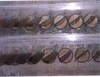
There have been many failures on the R0 stage blades of FA machines. These are the first blades after the IGVs. These failures have usually been initiated by water droplets (from washing or water injection) that notch the blade surface, leading to a high cycle fatigue failure, defined by characteristic chevron type markings followed by a blade tear. There have also been some failures on these same blades where the excitation of the blades is due to rotating stall at the inlet due to the nature of the inlet configuration.
There have been many problems due to notching on the blade surfaces leading to high stresses and blade failures. The smaller clearances (20-50 mils) and high pressure ratios tend to increase the probability of rubs. These tip rubs usually occur near the bleed flow sections of the turbines where there are inner diameter changes and the compressor casing tends to depart from being a perfect circle. Some manufacturers use an inner compressor casing ring, which can also lead to out of roundness problems and alignment problems between the rings and the casing, leading to blade tip rubs and trailing edge blade tip failures.
The advanced compressor blades also usually have squealer sections on the blade tips, which are designed to wear in a safe manner if the blades are in contact with the casing. These rubs, if severe, can lead to tip fractures and overall destruction of the downstream blades and diffuser vanes due to domestic object damage (DOD).
The high temperature at the exit of the compressor, which in some cases exceeds 1000°F, causes a hot compression section. This requires cooling of the bleed flows before they can be used for cooling the turbine section. This also limits the down time between start-ups of the turbines and also requires that the entire compressor section be coated.
Compressor coating has many benefits and is greatly recommended. It protects compressor blades and vanes from erosion and impingement of water especially in evaporative cooled or fogging systems. It also reduces skin friction and thus decreases the energy used in compression. In the latter stages it reduces the blade metal temperatures and thus lowers stress levels. This results in an increase in power available and improves the heat rate of the turbine. The extra cost of the coating, just in terms of fuel savings, is paid back in six months.
Table 2 shows changes in axial flow compressor design that we have seen in advanced gas turbines. The first column represents previous gas turbine designs, the second column represents new gas turbine designs, and the last column indicates the change in risk ( represents higher) resulting from the design differences. Most of the comparisons are self-explanatory.
Design margins are set by finite element modelling (FEM) at the element level which results in lower safety margins than previous designs. The costs of these larger, thinner, less-rub tolerant, and more twisted-shape airfoils are usually higher. When several of the major characteristics of advanced gas turbines are examined from a risk viewpoint (ie, probability and consequences of failure), there are no characteristics which reduce the probability of failure, and/or decrease the consequence of failure, thus careful inspection of the compressor section is a must.
Compressor deterioration in turbine performance is indicated by one or more of the following conditions:
• slower engine acceleration;
• engine compressor surge or stall;
• lower power output;
• loss of engine compressor discharge pressure; and
• increase in compressor discharge temperature.
During the first 5000 equivalent operating hours there is a sharp drop in delivered power and an increase in the turbine heat rate. These losses are non-recoverable in most cases, and would require the turbine to be returned to the shop and outfitted with most new components. The casing may need to be machined, as well.
Performance of the axial compressor is sensitive to the condition of the rotor blades (Table 3).* Dirt on blades, due to poor filtration and maintenance practices, can be a significant source of performance deterioration.
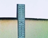
During a major inspection, all blades should be cleaned and checked for cracks with a dye penetrant test. Cracked blades should be replaced. In some cases, small cracks can be blended out. Tests conducted on blended blades have shown that if 75% of the chord length of the blade tip is intact then the compressor will suffer minimal loss of pressure and efficiency, and the blades can be used. The maximum and minimum chord lengths should be recorded and reported to the manufacturer, who will report back the performance loss and decrease in structural strength. On compressors having variable stators (usually limited to the first 3-5 stages), links should be checked for looseness which can cause wrong positioning of the stator blade leading to resonance in the rotor blades resulting in blade failures. Inlet Guide Vanes (IGV) are also very susceptible to failures for a similar reason due to their adjustment mechanism which allows for the changes in angle at various loads.
Compressor tip rubs can lead to blade failures at the trailing edge of the tip section of the blades. Most of these tip rubs usually occur near the bleed sections, where the cases are more susceptible to “out of roundness.” To ensure casing roundness measurements should be taken to determine blade tip clearances at four points on the circumference. Comparison of these clearance readings with those at installation or during a previous inspection will indicate if rubs have occurred and whether or not the casing is warped. The readings will also indicate whether or not the rotor is below its original position, and if further maintenance and adjustments are necessary.
If the air inlet is subject to salt-water contamination, the rotor and stator blades should be checked for pitting. Severe pitting near the blade roots may lead to structural failures, and the manufacturer should be informed of the condition. Coating compressor blades is recommended. The extra cost is paid back in the six months by the fuel savings which are result of the reduction of skin friction losses.
Cleaning the turbine compressor with the online wash system should be a routine and scheduled maintenance function. This system is based on injecting atomised demineralised water or a mixture with a cleaning fluid. Unless the plant operates in an area where the environment has considerable oil mist the use of demineralised water cleans as well as most cleaning fluid.
However, online cleaning is not the answer to all fouling problems. After each cleaning cycle, full power is not regained, and a time comes when the unit needs to be cleaned offline. This is done if the improvement in performance from offline cleaning can compensate the loss of income in power (due to shutdown) and the cost of labour for cleaning.
Requirements for water quality for both online and offline water washes are stringent, so as to ensure that impurities are not introduced (Table 4).
Testing the water quality is critically essential before performing a routine online water wash. This can be done by the use of a hand-held meter that measures conductivity, total dissolved solids and pH.