BOILER: Technolgy
Baima: China's first large-scale CFB
21 February 2004In the current context of China’s surging power demand and power capacity shortage, circulating fluidised bed (CFB) boilers are likely to play an increasingly important role. Such clean coal technology allows China to make use of its extensive coal resources in an environmentally friendly manner. Key steps are now being taken in acquiring the technology of large-scale (300 MW class) CFB power plants.
A major milestone in the process of circulating fluidised bed technology transfer is the Baima project, in Sichuan Province, China’s first large scale CFB. This is currently under construction and is expected to be complete in December 2005. It is a 300 MWe demonstration plant, with the specific purpose of proving Alstom’s capability to successfully design and build large-scale CFB boilers in China. Under a u65 million contract, Alstom is supplying the CFB, in co-operation with Dongfang Boiler, with the engineering done in France and the manufacturing being shared between Alstom and Dongfang facilities.
Other milestones in the process involve two technology transfer agreements with the three main Chinese boiler manufacturers, Dongfang, Harbin and Shanghai Boiler and with ten Chinese electric power design institutes. These agreements have a duration of 15 years and will allow domestic manufacturers to supply units in the output range 200-350 MWe exclusively in China.
The choice of Alstom’s CFB technology is the conclusion of a series of evaluations conducted by Chinese experts further to an international competition lasting several years (launched in November 1997) and is based on both technical and economic criteria.
Following the signing of the contracts, on 31 March 2003, each of the three Chinese boiler makers (who are all Alstom licensees), have to execute a “co-production” project. The three co-production projects are to be constructed jointly by Alstom and one of the three licensees and represent the next phase of the technology transfer process, the aim being to ensure effective implementation of CFB technology in China.
In October 2003, Alstom received from Harbin the order for the first of the co-production projects. This is the Kaiyuan plant,
in Yunnan Province. It will consist of two
lignite-fuelled 300 MWe CFBs. The units
will be located 1200 m above sea level, and to achieve the 300 MWe rating for this
fuel at this altitude the CFBs will be among the largest ever constructed, in terms of
physical dimensions.
Alstom expects to receive an order from Dongfang for the second co-production project, Qinhuangdao in Hebei Province, in the near future. This will also consist of 2x300 MWe CFB units, burning bituminous coal.
An order for the third co-production plant, from Shanghai Boiler, is expected in the next few months.
In addition there are many other 300 MWe CFBs projects in China planned for implementation on the co-production or licence basis, with substantial opportunities for further development in the CFB field.
Meanwhile at the Baima site good progress is being made. Construction started in May 2003 and is going smoothly. Civil works for boiler foundations and turbine hall are close to completion.
The Baima plant is being constructed for Sichuan Baima CFB Demonstration Power Plant Co Ltd, whose main shareholders are State Power Grid and Sichuan Bashu Electric Power Development. The plant is expected to help reduce power shortages in Sichuan Province and is strongly supported by the local and central authorities.
Baima CFB design
The Baima steam conditions (at BMCR) are as follows:
Main 1025 t/h
steam flow (2 259 738 lb/h)
Main steam
pressure 17.4 MPa (2538 psig)
Main steam
temperature 540°C (1004°F)
Reheat 843.93 t/h
steam flow (1 856 646 lb/h)
Reheat steam
pressure 3.706 MPa (540 psig)
Reheat steam
temperature 540°C (1004°F)
Feedwater
temperature 281°C (538°F)
The natural circulation Baima CFB boiler is designed to fire a Chinese anthracite coal, which has a relatively low volatile matter content (8.5% as received) and a high ash content (35% as received). The calorific value is 18495 kJ/kg (7946 Btu/lb). The detailed analysis is:
Design coal Check coal
Carbon 49.2% 44.2%
Volatile 8.55% 9.35%
matter
Sulphur 3.54% 4.3%
Ash 35.27% 38.1%
Moisture 7.69% 9.5%
LHV 18495 kJ/kg 17040 kJ/kg
(7946 Btu/lb) (7321 Btu/lb)
Hardgrove 79 77
The gases discharged at the stack will meet the following guaranteed emissions requirements (@ 6%O2, dry) without any post-combustion cleaning equipment for NOx or SOx:
SO2 600mg/Nm3
NOx 250mg/Nm3
The boiler thermal efficiency, including the heat credits, is higher than 91% (LHV).
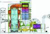
The design itself uses concepts developed and well proven over several years of successful operation at the Provence (1 x 250 MW) and Red Hills (2 x 250 MW) CFBs (the latter serving one turbine of 500 MW). Features include pant-leg furnace, four high efficiency cyclones and four external heat exchangers, two for bed temperature control and two for reheat steam temperature control.
Fuel feed system. Fuel is extracted from four fuel silos at variable rates, as required
by the operation of the boiler, by gravimetric feeders. From the feeders, the coal is fed,
via four parallel feed systems, into the four seal pots.
Limestone milling system. One limestone milling system is provided to deliver properly crushed sorbent product. Secondary limestone crushing is achieved with hammer mills. The appropriate limestone grain size is obtained by solids recirculation through vibrating screens. The system is designed to match the limestone particle size requirements and limestone capacities for optimum in-furnace desulphurisation.
Limestone injection system. Two parallel pneumatic limestone injection systems are provided. The limestone from each injection system line is injected into the furnace through four points located in the return leg from the seal pot to control the SO2 emissions at the stack outlet.
CFB furnace. The furnace consists of waterwalls that are lined with refractory to a height of about 9 m above the grates. Two cooled primary air plenums are provided below the furnace, and feed primary air to the fluidising grates and the pant-leg bottom of the furnace. Fluidising nozzles are located in the floor of the furnace. Openings are provided in the refractory lined lower furnace for secondary air, solids return from the seal pots and EHEs, and instrumentation. In-furnace evaporator wall extension panels are located in the upper furnace to perform the additionally required evaporator duty.
Solids recycle system. Flue gas with entrained solids enters the four parallel recycle cyclones specially designed for high separation efficiency. The collected solids flow downward into a standpipe, ending in four refractory-lined air-fluidised siphon seal pots. The siphon seal pot arrangement returns part of the solids separated by the cyclones through an inclined refractory-lined duct to the lower furnace section. The remaining solids are diverted from each of the siphon seal pots into the external fluid bed heat
exchangers via the siphon seal ash
discharge valves.
Convective backpass. Flue gas enters the convective backpass after exiting from the recycle cyclones, which reduce the solids carry-over to the convective section. Heat is transferred from the flue gas to the steam and water circuits, which are made up of superheater, reheater, and economiser surfaces.
Ljungstrom air preheater. Primary and secondary air leaving the PA fan and SA fan are heated by the Ljungstrom air preheater. The Ljungstrom quadrisector regenerative air preheater design is a highly efficient, rotating semi modular element, compact heat exchanger.
External heat exchangers. The EHEs provide the required additional heat transfer surface external to the combustion chamber. A portion of the circulating solids is fed to the EHEs where sensible heat is transferred to the steam system. Since the feed rate of solids is controlled, optimum furnace conditions and steam temperatures can be maintained, irrespective of fuel type and/or load. The design incorporates two EHEs containing the intermediate superheater, and two EHEs containing the finishing reheater and low temperature superheater.
Air and gas system. The combustion air is supplied to the CFB furnace in two main streams: primary air and secondary air. Primary air is introduced into the two windboxes of the pant-leg through two separated ducts, the air flowrate is controlled in each leg by appropriate dampers. The secondary air is injected into the lower furnace through various ports in the walls. Fluidising air for the EHEs and fluidised bed ash coolers is provided by the fluidising air fans. The gas flow through the system is generated by the induced draft fan, which is located downstream of the electrostatic precipitator. Two primary air fans, two secondary air fans, are supplied. Five fluidising air fans are provided, including one spare.
Burner system. The CFB burner system used for preheating the unit is composed of in-duct burners fired with Chinese diesel oil, associated with oil lances located in the bottom of the furnace
Emissions control system. NOx is controlled by the furnace air staging and the controlled temperature combustion. SO2 control is achieved by limestone injection in the furnace. Particulate control is via an electrostatic precipitator (ESP).
Ash removal system. Bottom ash is removed by four fluidised bed ash coolers and transported by mechanical means to the bottom ash silo. The fly ash is conveyed pneumatically from the convective back pass hoppers and the electrostatic precipitator ash disposal bins.
CFB advantages
In selecting circulating fluidised bed technology for Baima, the owners gain certain specific operational and cost advantages compared with the downshot pulverised coal boilers traditionally used to fire Chinese anthracites.
The first advantage is in terms of minimum load without oil support, usually referred to as “technical minimum.” The technical minimum guaranteed for Baima is 40%. PC boilers firing anthracite have in many cases a higher technical minimum. The difference amounts to considerable fuel oil savings during part load operation.
Also, post-combustion equipment (such as SO2 scrubbers and selective catalytic reduction (SCR) would be mandatory downstream of a PC boiler, but is avoided in the CFB case, thus reducing CFB investment costs and increasing ease of operation. SCRs, which consume ammonia for NOx reduction, are employed in pulverised coal boilers – but there is no need for this in the CFB combustion process. Another significant advantage is fuel flexibility: CFB boilers can accommodate the considerable variations in fuel quality that are likely to happen over the plant’s life.
TablesAlstom 100+ MW CFB experience