Designing SCR systems for high-dust applications

-
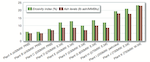
Figure 2. Erosivity index (%) and ash levels (lb ash/MMBtu) for selected... -
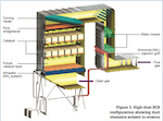
Figure 3. High-dust SCR configuration showing duct elements subject to erosion -
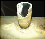
Figure 4. Severe AIG lance erosion -
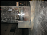
Figure 5. Ammonia injection grid lance showing protective wear shield... -
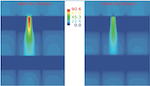
Figure 7. Excessively high velocity associated with a 1” x 1” gap between... -
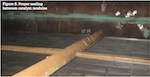
?Figure 8. Proper sealing between catalyst modules -
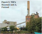
Figure 9. TSE’s Naantali unit 3, Finland -
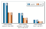
Figure 1. New NOx limits for Indian thermal power plants call for SCR on new... -
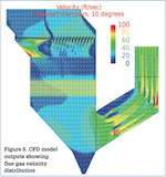
Figure 6. CFD model outputs showing flue gas velocity distribution

