BIOMASS COMBUSTION
German CFBs prove match for wood waste
23 June 2004Three new wood-fired CFB units in Germany, at Kehl, Papenburg, and Königs Wusterhausen, have performed well, fully meeting strict emission limits.
Under the German Biomasseverordnung legislation, a subsidy starting at 0.087/kWh from 2002 onwards and reducing by 10% for each subsequent year over 20 years is being paid for electricity from new biomass-fired plants rated at up to 20 MWe. This has led to the building of a number of new plants, among them three CFB-based units contracted to Foster Wheeler in 2001 (listed in Table 1). Two of the customers for these units, Harpen Energie Contracting GmbH and Prokon Nord Energiesysteme GmbH, have subsequently ordered follow-on units, for completion in 2005.
Thanks to the number of new plants coming on stream and projected, the availability of wood and wood waste is becoming increasingly restricted, however. By 2005, it is predicted that up to six million tonnes could be required in Germany alone, while actual available material is estimated to be of the order of four millions tonnes. Fuel quality, in particular, is rapidly becoming an issue, with the availability of better-grade material declining. Only plants offering high efficiency, high availability, and the capability of handling large fluctuations in fuel quality effectively, therefore, have the potential to operate cost-effectively in this type of situation.
Wood-based fuels increase the risk of slagging and fouling of heat transfer surfaces, and the risk of fireside corrosion as well, which places exacting demands on boiler design. While bubbling fluidised bed (BFB) designs offer a number of benefits, and continue to be ideal for applications in the forest products industry, for example, CFB technology offers more for small-scale utility use.
CFB advantage for wood
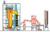
Advances such as Foster Wheeler's integrated solids separator have enabled solids separators, recirculation systems, and furnaces to be built as integrated cooled panels, resulting in reduced plant footprints and lighter refractory. The use of Intrex integrated heat exchangers, located in the lower part of the combustion chamber outside the main combustion area and away the flue gas flows, which generally contain the most harmful components, enables high superheating temperatures to be achieved, thanks to a largely corrosion-free environment. Intrex superheaters also enable fuels with a high chlorine content to be used that would cause superheater tubes to be easily corroded or fouled in a conventional design.
Using the Intrex concept, the final superheater and reheater can be placed in the hot solid return flow from the cyclone to the combustion chamber, avoiding the problems of high-temperature fireside corrosion. This allows the steam temperature after the superheater in the flue gas pass to be kept below 400°C. Typically, the steam temperature after a final Intrex superheater is between 480 and 500°C, at about 90 bar for demolition wood, and even higher for untreated wood. As a result, generating efficiency can be raised from 25-30%, typical of a conventional design in condensing mode, to 35.5% with a non-reheat steam cycle, and up to 36.5% (gross) with reheat.
The use of Intrex units also has benefits in terms of maintenance, as surfaces can be replaced, if needed, in a matter of only a few days, keeping outages and costs to a minimum.
Foster Wheeler's Step Grid (see illustration above), featuring directional nozzles to create horizontal jets of air and large solids discharge openings, is also a particular plus when firing demolition wood and waste, as it helps guarantee good fluidisation and ensures that heavy metal objects that enter the furnace, such as nails, bolts, hinges, and other items such as stones, exit with the bottom ash.
Particular attention in all three designs has been paid to fuel feeding. To ensure smooth fuel feeding, efficient crushing and chipping systems have been specified, together with metal removal. Given the 10%-60% variation in moisture content of wood waste, efficient homogenisation in the fuel yard is a necessity to ensure steady heat input into the boiler using volumetric feeders.
Three configurations
The Köhler Kehl boiler island was the first of the three Foster Wheeler CFB plants ordered in 2001 to be completed, and was the first new plant in Germany to be commissioned and benefit from the Biomasseverordnung legislation after it came into force. The unit follows on from Foster Wheeler's first two CFBs fired on waste wood in Germany: Hornitex Beeskow (1996 start-up, 86 MWt, 110 t/h, 480°C, 89 bar) and Hornitex Horn-Bad Meinberg (1999 start-up, 94 MWt, 120 t/h, 480°C, 89 bar). Both of these have performed well with very high availability and emissions well below 17.BlmSchV requirements, firing wood processing residues and demolition wood.
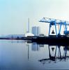
The Köhler Kehl plant, which was started up at the end of 2002 and completed its acceptance tests in February 2003, is located at Kehl on the Franco-German border, and supplies a paper mill operated by August Köhler AG with power and steam. The CFB boiler island generates about 60 t/h steam at 90 bar and 500°C, and an associated steam turbine generates 8.6 MW of electricity with a back pressure of 7.5 bar.
Designed to fire around 80 000 t/a of Class A1 to A4 demolition wood, forest wood residue chips, sawdust, and shavings, it is currently licenced to burn Class A1 and A2 material. Like all other Foster Wheeler CFB boilers fired on wood waste, the plant does not require SNCR or SCR to control NOx emissions. Flue gas cleaning is based on absorption injection and a bag filter, with calcium hydroxide used for absorption and active carbon for absorbing mercury and heavy metals – meeting 17.BlmSchV requirements.
Prokon Nord Energiesysteme's plant, based on a Foster Wheeler CFB boiler island, at Papenburg in northwest Germany began operation in June 2003. Initially designed to generate 20 MWe of power, the plan is to generate steam for district heating purposes from mid-2004 onwards. The plant fires all four classes of demolition wood (A1-A4), and its approximately 150 000 t/a fuel requirement is delivered by a combination of barge, rail, and road.
In contrast, the third unit, at Königs Wusterhausen near Berlin, and supplied to MVV Energie AG, was a turnkey power plant delivery, incorporating a reheat boiler, giving a very efficient steam cycle and a total gross plant efficiency of 36.4%, well above the official minimum of 29% set for 15-20 MWe plants under Germany's biomass legislation. Fuel consumption is reduced by a factor of 25% as a result, benefiting the plant in the future, given escalating fuel costs.
The unit's CFB boiler is specified to generate 64 t/h of steam at 64 bar and 477°C. The steam is superheated in two Intrex units, and reheated between the high-pressure and low-pressure sections of the turbine. This steam runs a condensing turbine with a wet cooling tower and a generator with a nominal electricity output of 20 MW. Fuel consists of some 120 000 t/a of A1-A4 material, again delivered by barge, train, and truck.
Flue gas cleaning features a two-stage concept, based on a multicyclone for pre-dedusting and dry injection of calcium hydroxide and active carbon, and dedusting and removal of emissions in the absorption filter. To reduce the need for absorption material, recirculation is also employed.
Fuel quality variations
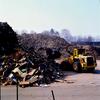
With the growing demand for biomass, it is perhaps no surprise that fuel deliveries at all three plants include impurities, such as metal and large amounts of plastic, stones, glass, and similar materials. Metal is often combined with larger pieces of wood, and cannot be separated using normal metal detectors. Women's tights, cable, and wire have also been present in some deliveries, despite the fact that the four-stage classification system under which the fuel is sourced makes no reference to other materials of this or any other type, only to
levels of impurities.
Large amounts of stones or large individual stones can cause erosion problems in fuel preparation systems, and hamper fluidisation in the combustion chamber. While fluctuations have been larger than expected,
no major problems adversely impacting overall performance have been encountered. Experience shows, however, that monitoring the quality of fuel before it enters the
fuel preparation stage to ensure that it stays within specifications is the best way of
guaranteeing performance and minimising the potential for lower heat value and higher ash content.
Waste from mechanical wood-processing, together with recycled waste wood, contains impurities not typical of natural wood, including elevated concentrations of alkalis, heavy metals, chlorine, and sulphur and nitrogen compounds. Due to the relatively low combustion temperature in a CFB, typically between 800 and 900 °C, NOx emissions can be controlled through good mixing and effective air staging. Good mixing and long residence time in hot, uniform conditions are very favourable for CO2 and hydrocarbon burn-out. Low hydrocarbon emissions are a precondition for low PCDD/F emissions.
A relatively low combustion temperature reduces the decomposition of minerals and the volatilisation of metals. CFB ash is porous, and the fraction of fused minerals is low. A dust filter controls heavy metal emissions.
Stack emissions at all three new German plants have clearly been below guarantee values. Emission values for HCl and SO2 are inherently low, and have been very low compared to other boiler concepts. As a result, absorption material consumption has been lower than predicted. Detailed performance at different loadings at one of the new plants is shown in Table 2.
All in all, the three new plants, and the two similar projects now underway elsewhere in Germany, confirm the potential of CFB in firing biomass such as demolition wood and wood residue.
TablesTable 1. Three Foster Wheeler CFB plants ordered in 2001, all now in operation Table 2. Performance of Foster Wheeler CFB (firing demolition wood)