Transmission & Distribution
Investigating the FACTS in Turkey
1 May 2007Enhancing the stability and reliability of Turkey’s transmission network first required a thorough test of a UPFC system. Its performance was assessed on one of the country’s most overloaded lines.
Flexible AC transmission systems (FACTS) are used worldwide to solve static and dynamic control problems associated with power lines, mainly because they offer a degree of planning and control that is essential to achieving good quality, reliable power.
But there is no field application of such a system in Turkey’s transmission grid. Consequently it was necessary, in order to assess the effectiveness of FACTS, to study a specific case in simulation and make a comparison with a classical power flow controller – in this case a phase shifting transformer. In the assessment the most important generation and consumption areas of the system and the heavily loaded transmission lines between them were studied, and a fault analysis for the studied system made. Ultimately, the important control objectives of preventing loop flows and managing balanced load sharing were achieved.
The necessity for this arose mainly from a principal feature of Turkey’s transmission network – the long-distance transfer of power from regions with surplus generation to those where industrial growth is most concentrated. Economic aspects played a dominant role in the building of these lines. This geographical dispersal of generation and load results in very large power flows through long lines, and line trips occur frequently. And wide variations of the load flow may lead to dangerous situations in which small-signal stability is lost and inter-area oscillations occur, and that can affect the whole interconnected power system.
Creation of the 380 kV transmission system started around ten years ago. Following construction, steady state analyses were performed. The system’s critical power flow paths and bottlenecks were determined and a UPFC system (unified power flow controller, a member of the FACTS family) which can independently control active and reactive power flows on the line as well as the bus voltage, was applied to these sectors in an attempt to manage power flows and to prevent loop flows.
Generation statistics
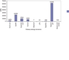
During the last 10 years Turkey’s installed power capacity which stood at 36 856 MW in 2005, has doubled, and is estimated to reach 65 000 MW in the year 2010. Total electricity generation for the year 2004 was 149.6 billion kWh. According to the Government Statistics Institute (DIE), 69.19 % of this total was supplied from thermal power plants, with the contribution from wind and hydro power plants standing at 0.04% and 30.77% respectively. 40.86% of the country’s electricity is generated by Electricity Generation Incorporation (EUAS), 35.75% by cogeneration plants, 15.32% by independent producers and 8.07% by affiliated partnerships of EUAS. The distribution of generation in 2004 by primary source and percentage is shown in Figures 1 and 2.
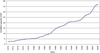
Today, Turkey’s electricity generation totals approximately 150 million MWh per year and will be 400-500 million MWh per year by the year 2020. The incremental development of Turkey’s installed capacity is shown in Figure 3.
Transmission system
Turkey’s electricity supply system can be described under three main headings – electricity production, transmission, and load. The system is divided into 21 regions. System voltages are 380, 154 and 66kV. Transmission network components and lines* are described in Table 1. On 28 September 2005 Turkey signed an operational agreement with UCTE (the Union for the Coordination of Transmission of Electricity).
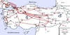
Although Turkey has no synchronous operation with other countries it does have many interconnections, such as those with Azerbaijan, Bulgaria, Romania, Iraq, and Syria. The structure of its 380 kV system is shown in Figure 4. In 2003 the maximum power load was measured at 21 539 MW and the minimum at 13 380 MW, translating as a 60% load variation during the year. Daily consumption figures for 2004 confirmed this, standing at 469 439 MWh (maximum) and 260 261 MWh (minimum).
It is mainly that the country’s hydroelectric plants are widely spread that has led to a high proportion of power being transmitted over long transmission lines. There are three main hydro power plants – Keban, Atatürk and Karakaya – in the system. Their output is transmitted via series capacitors to load centres located in the west of the country. The result is that power flows by unintended routes through unsuitable lines to where it is needed and sometimes loop flows occur.
Transmission system faults can also be indicators of system stress. Table 2 shows faults on the 380 kV and 154 kV networks, and, as can be seen, they are not distributed according to seasonal conditions.
Real system investigatIon
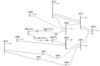
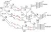
A considerable amount of power is generated at the three hydro power plants Keban, Atatürk and Karakaya. This power is transmitted through Ankara to the Istanbul load region. Figure 5 shows the diagram of this region. It also indicates (figures shown in boxes) the number of trips in a year.
Two methods of power flow control were compared for their effectiveness in eliminating loop flows, distributing the load, and controlling the power flow of the region generally. One was the classical phase shifting transformer (PST) system and the other the more developed system in the FACTS family known as a unified power flow controller (UPFC) which is capable of controlling both active and reactive power along lines. The tool used was SIMPOW, a highly integrated application for simulation of power systems. It covers a wide field of network applications focusing on dynamic simulation in the time domain and analysis in the frequency domain.
Phase shifting transformers
As power systems get more complex and more stressed, appropriate tools to control the power flow within a given network are increasingly required. Phase shifting transformers can control power flow in a complex power network in a very efficient way. The phase angle variation depending on loading can be expressed as follows:
In this expression:
Da defines phase angle variation according to load current,
ifkt indicates the PST current in pu
xfkt indicates the PST impedance in pu
Y describes the angle between load voltage and load current. Low xfkt decreases this effect.
UPFC
A regular unified power flow controller consists of two voltage source converters with a common DC capacitor as shown in Figure 6. One voltage source converter (VSC1) operates as a static VAr generator and is able to control the AC voltage –Uac1 on the network side of its converter transformer, and the DC voltage of the capacitor.
The second voltage source converter (VSC2) is connected to the network by means of a converter transformer with its network winding in series with a transmission line. The voltage across the series winding, (–Us), can be varied, magnitude and phase, by means of the controllable AC voltage of VSC2.
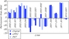
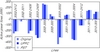
Figure 7 shows the location considered best for the UPFC and Figure 8 the power flow variations after applying it. The main generation source is at bus 3002, which is also the whole transmission system slack bus. Owing to line reactance and because the series capacitors are not of a controllable type, huge loads are transmitted along the line between busses numbered 3001-3006 and 3001-3007. This also creates an unintended loop flow between busses 3002 and 3003. The main objective is to decrease power flow from 436 MW to 300 MW between busses 3003 and 3002 which means no loop flow and equal power flows between parallel lines having series capacitors. To satisfy this condition a UPFC series voltage 0.4 pu in magnitude with a 60° angle difference must be applied to line. For a PST it is found that the same power flows can be obtained for a 17° phase difference. In Table 3, a comparison between bus voltages at normal system conditions and formed bus voltages after UPFC and PST have been applied are shown and a graphical comparison is given in Figure 9.
Results
By imposing power flow control with either a PST or a UPFC system the loading of the line between busses 3003 and 3002 is decreased, so that no loop flow occurs and power flows from those parallel lines with series capacitors are better balanced.
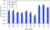
Judging by the power flow results (Table 4, Figures 10, 11) it can reasonably be said that the PST system is as effective as the UPFC. The UPFC increased bus voltages to approximately 1 pu by virtue of its capability of independent reactive power control with its voltage source converter. For this application the PST, which costs less to install, could be more appropriate, but for longer and more heavily loaded lines in the transmission system, control of active power requires a greater reactive power component, a need that can be more effectively met with a UPFC system.
Figure 1. Distribution of electricity generation by primary energy resource to 2004 Figure 2. Percentage of electricity generation by primary energy resource to 2004 Figure 3. Annual development of Turkey’s installed capacity Figure 4. Turkey’s 380 kV transmission system (Source: TEIAS, APK 2003) Figure 5. Investigated 380 kV (real) system Phrase angle variation expression Figure 8. Power flow variation after applying UPFC to the investigated system Figure 7. UPFC location in investigated system Figure 9. Bus voltages for the investigated system for UPFC and PST Figure 10. Active power flow comparison for UPFC and PST Figure 11. Reactive power flow comparison for UPFC and PST