nuclear power
IRIS flowers from light water stock
31 July 2006For nuclear power to achieve its potential, reactor designs must be quicker to deploy, more economic and safer than ever before. IRIS is the most advanced of a new breed of light water reactors offering safety features not due for 20 years on Generation IV designs.
Nearly three decades after the Three Mile Island incident put an end in the USA to orders for new reactors, a new era for nuclear power is upon us. A fresh breed of reactor designs will power the upcoming nuclear age. Since a meaningful contribution from the Generation IV designs is not expected before 2030 at best, nuclear electric power in the next two decades will mostly come from the mainstay light water cooled reactors, with contributions from heavy water and gas cooled reactors. In any event, the incoming reactor designs will be different from the ones currently in operation. Generally speaking, the longer a design remained on the drawing boards, the closer it is to the current reactors. Among the light water reactors’ new designs, the ‘youngest’ and thus the most different from today’s is IRIS (International Reactor Innovative and Secure).
Even though IRIS development started only in October 1999, the project has moved rapidly forward, with the goal of deploying the first units around 2015 (Table 1).
The IRIS project philosophy is based on economy and safety, with simplicity as the cornerstone: a simple design is more economic and at the same time safer (fewer components and systems to go wrong). It seems obvious, but let’s remember that after Three Mile Island, increased safety was implemented through additional components and increased costs. As will be seen, in IRIS increased safety is achieved by eliminating components.
Furthermore, since IRIS is based on proven light water reactor technology, it does not require technology development and prototype demonstration. Appropriate testing will be conducted to verify the significant engineering changes which embody the simplicity of the IRIS approach. Thus, the development timetable is compact and predictable, avoiding the pitfalls always present with a new and unproven technology.
A significant impetus to the IRIS project was given on 6 February 2006 by the US Department of Energy (DoE) when its major new nuclear initiative, the Global Nuclear Energy Partnership (GNEP) was unveiled. One of its elements is the development of small-scale reactors for “safely expanding nuclear energy in developing nations and small-grid markets without increasing proliferation concerns… These reactors will be safe, simple to operate, more proliferation-resistant and highly secure … The GNEP seeks to form international partnerships to accelerate certification of marketable designs, and deploy operational demonstration plants.” In the GNEP programme description, the DoE singled out IRIS as an example of such a small reactor.
Integral NSSS design
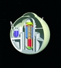
IRIS is a pressurised light water cooled integral design where all the primary system components are located within the reactor vessel. This is not an IRIS innovation, because many other similar designs preceded it, starting with the Swedish PIUS in the mid to late 1980s, followed by the Anglo-American SIR, the Argentinian CAREM, the Italian ISIS, and the South Korean SMART, to name a few. The innovative characteristics of IRIS are that every primary system component is integrated in the vessel (IRIS is the only design to have fully internal primary pumps), the containment is designed to be thermodynamically coupled with the integrated primary system during accident conditions, and the overall design is focused first and foremost on simplicity. The IRIS integral layout is shown in Figure 1; its major design parameters are summarised in Table 2.
Primary system
The IRIS reactor vessel (RV) houses not only the nuclear fuel and control rods, but also all the major reactor coolant system (RCS) components: eight small, axial flow, reactor coolant pumps (RCPs); eight modular, helical coil, once through steam generators (SGs); a pressuriser located in the RV upper head; the control rod drive mechanisms (CRDMs); and a steel reflector which surrounds the core and improves neutron economy, as well as providing additional internal shielding. Water flows upwards through the core and then through the riser region (defined by the extended core barrel). At the top of the riser, the coolant is directed into the upper part of the annular plenum between the extended core barrel and the RV inside wall, where the suction of the reactor coolant pumps is located. The flow from each pump is directed downward through its associated steam generator. The primary flow path continues down through the annular downcomer region outside the core to the lower plenum and then back to the core, completing the circuit. Because the IRIS integral vessel contains all the RCS components, it is larger than the RV of a traditional loop-type PWR. However, this integral RV arrangement eliminates the individual component pressure vessels and large connecting loop piping between them, resulting in a more compact configuration and in the elimination of large loss-of-coolant accidents as design basis events.
Pressuriser
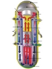
The IRIS pressuriser is integrated into the upper head of the reactor vessel (Figure 2). The pressuriser region is defined by an insulated, inverted top-hat structure that divides the circulating reactor coolant flow path from the saturated pressuriser water. Heater rods are located in the bottom portion of the inverted top-hat which contains holes to allow water to surge in and out of the pressuriser region.
By using the upper head region of the reactor vessel, the IRIS pressuriser provides a very large water (~71m3) and steam (~49m3) volume, as compared to plants with a traditional, separate, pressuriser vessel. The steam volume is about 1.6 times greater than the AP1000 pressuriser steam space, while IRIS has less than one third the core power. Thus, the volume to power ratio is about five times larger in IRIS, allows the elimination of pressuriser sprays, which are used in current PWRs to prevent the pressuriser safety valves from lifting for any design basis heatup transients.
Reactor core
The IRIS core and fuel assemblies are similar to those of loop-type Westinghouse PWRs. Specifically, the IRIS fuel assembly is similar to the Westinghouse 17x17 XL Robust Fuel Assembly design and AP1000 fuel assembly. Low-power density is achieved by employing a core configuration consisting of 89 fuel assemblies with a 14-foot (4.267m) active fuel height, and a nominal thermal power of 1000 MWt. The resulting average linear power density is about half of the AP1000 value. The improved thermal margin provides increased operational flexibility, while enabling longer fuel cycles and increased overall plant capacity factors.
The IRIS core will use UO2 fuel, enriched to 4.95% in U-235. The fission gas plenum length is increased (roughly doubled) compared to current PWRs, thus eliminating potential concerns with internal overpressure. The integral RV design permits this increase in the gas plenum length with practically no penalty, because the steam generators, rather than the fuel assembly, mainly determine the reactor vessel height.
Reactivity control is accomplished through solid burnable absorbers, control rods, and the use of a limited amount of soluble boron in the reactor coolant. The reduced use of soluble boron makes the moderator temperature coefficient more negative. The core is designed for approximately a three-year cycle with half-core reload to optimise the overall fuel economics while maximising the discharge burnup.
Reactor coolant pumps
The axial flow IRIS RCPs are of a ‘spool type’, which has been devised for marine applications, as well as for chemical plant applications requiring high flow rates and low developed head. The motor and pump consist of two concentric cylinders, where the outer ring is the stationary stator and the inner ring is the rotor that carries high specific speed pump impellers. The pump is located entirely within the reactor vessel, with only small penetrations for the electrical power cables since the use of high temperature motor windings and bearing materials eliminates the need for cooling water and the associated piping penetrations through the RV. The spool pump geometric configuration maximises the rotating inertia and these pumps have a high run-out flow capability; both these attributes mitigate the consequences of loss-of-flow accidents (LOFAs). Because of their low developed head, spool pumps have never before been considered for nuclear applications. However, the IRIS integral RV configuration and low primary coolant pressure drop can accommodate these pumps and take full advantage of their unique characteristics.
Steam generators
The IRIS SGs are a once-through, helical-coil tube bundle design with the primary fluid outside the tubes. Eight steam generator modules are located in the annular space between the core barrel and the reactor vessel. Each IRIS SG module consists of a central inner column which supports the tubes, the lower feedwater header and the upper steam header. Each SG has 656 tubes, and the tubes and headers are designed for the full external RCS pressure. The helical-coil tube bundle design is capable of accommodating thermal expansion without excessive mechanical stress, and has high resistance to flow-induced vibrations. This type of SG was successfully tested in Italy by Ansaldo in an extensive investigation conducted on a 20 MWt full diameter, part height, test section. The performance characteristics (thermal, vibration, pressure losses) were investigated as was the operating domain for stable operation.
Control rod drive mechanisms
The integral configuration is ideal for locating the control rod drive mechanisms (CRDMs) within the vessel, in the region above the core and surrounded by the steam generators, yielding significant advantages in safety and operation.
Concerning safety, the rod ejection accident (a Class IV accident) is eliminated because there is no potential 2250 psi (15.25MPa) differential pressure to drive out the CRDM extension shafts. Operationally, the absence of CRDM nozzle penetrations in the upper head eliminates all the operational problems related to stress corrosion cracking of nozzle welds and seals which have intermittently plagued the industry and incurred heavy economic penalties. IRIS has no penetrations in the upper head (except for the automatic depressurisation system safety valves piping) so the design and manufacturing of the upper head is also simpler and cheaper.
Neutron reflector
IRIS features a stainless steel radial neutron reflector to reduce neutron leakage, thereby improving core neutron use, and enabling an extended fuel cycle and increased discharge burnup. The radial reflector has the added benefit of reducing the fast neutron fluence on the core barrel, and, together with the 1.7m-thick downcomer annulus, reduces the fast neutron fluence on the reactor vessel very significantly (by a factor of 105), in turn reducing the vessel activation and the dose outside the vessel. This has obvious beneficial impacts on costs (very long life vessel, no need for the embrittlement surveillance programme, reduced biological shield), operational doses, and decommissioning.
Maintenance
While the integral IRIS configuration offers improved design and performance compared with the conventional loop configuration, what about the monitoring and maintenance of these in-vessel components?
Significant effort has been expended to address this question and the result is that the IRIS maintenance regime is better than in current and advanced LWRs to the extent that for IRIS the scheduled maintenance interval can be extended up to 48 months, to match, with margin, the upper limit of the core burn capability. This is obtained, first and foremost, by designing the IRIS primary system components to have very high reliability, reducing the frequency of inspections and repairs.
The basis for maintenance optimisation was an earlier study by the Massachusetts Institute of Technology to identify required actions to extend the maintenance period of an operating PWR from 18 to 48 months or to perform maintenance and testing online. MIT identified 3743 maintenance items, 2537 offline, 1206 online. It was possible to extend 1858 of the offline items from 18 to 48 months, while 625 could be recategorised from offline to online.
This left 54 items which still needed to be performed offline on a schedule shorter than 48 months. Starting from the MIT study and factoring in the specific IRIS conditions (eg, type of RCP), only seven items were left as obstacles to a 48-month cycle. They have been addressed, and either resolved or assigned a plan of action.
Because of the longer cycle burn and the four-year maintenance cycle capability, the personnel requirements are expected to be significantly reduced and the capacity factor will comfortably satisfy and exceed the 95% target. Both considerations will result in decreased O&M costs.
Containment
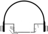
Complementing the integral primary system design is the patented containment design. The IRIS containment is a 25m diameter high design pressure spherical steel structure with a steam suppression system, and it combines the best characteristics of PWR and BWR containment (Figure 3). The greatly reduced containment footprint is due to the integral RV configuration, which eliminates the reactor coolant system loop piping and external steam generators, pumps and pressuriser along with their individual vessels. This size reduction, combined with the spherical geometry, results in a design pressure capability three to four times higher than for a typical PWR cylindrical containment, assuming the same metal thickness and stress level in the shell.
The pressure suppression pool limits the containment peak pressure to well below the containment vessel (CV) design pressure and its elevation provides a source of short term gravity-driven makeup water to the RV. The containment internal structure forms a below ground flood up cavity which contains the lower nine metres of the reactor vessel where the core is located, thus ensuring that the core is surrounded by water following any postulated accident. The water flood-up height is sufficient to provide long-term gravity makeup, so that the RV water inventory is maintained above the core for an indefinitely long period of time.
Almost half of the IRIS containment vessel is located below ground, leaving only about 15m above the ground and resulting in an exposed area several times less than for the containment of a traditional LWR. This very low profile makes IRIS an extremely difficult target for an airbourne assault; in addition, the IRIS containment is housed in and protected by a cylindrical reactor building.
The most innovative feature of the IRIS containment, which is also an excellent example of embodiment of the simplicity-driven design philosophy, is how the containment and primary vessel become coupled during a loss of coolant accident (LOCA) and intrinsically terminate the transient. While large LOCAs are eliminated in an integral configuration, small/medium LOCAs can still occur since a few vessel penetrations cannot be eliminated. During a postulated small/medium LOCA the large heat transfer surface of the steam generators located inside the vessel is used to remove the heat produced in the core and condense the produced steam, thus depressurising the vessel. At the same time, during the initial phase of the transient, the pressure in the high design pressure IRIS containment is allowed to rise to levels substantially higher than possible for a loop PWR. The combination of simultaneous pressure decrease inside the vessel and pressure increase inside the containment would quickly decrease the pressure differential across the break, which is the driving force for the coolant loss. After 30-60 minutes, depending on the LOCA conditions, the break pressure differential would become zero and the coolant egress stops automatically. The vessel and the containment are then thermodynamically coupled through the break and act as a single system. The pressure suppression system keeps the containment pressure from rising further while outside cooling of the containment provides the controlling ultimate heat sink. Because of the very large coolant inventory, the core remains well covered throughout the entire transient, without any need for external water makeup, either by active or passive means.
Thus, IRIS does not need and does not have a dedicated safety injection system for emergency core cooling; this system is eliminated together with all its auxiliary systems.
Safety approach
The handling of the small LOCAs above embodies the IRIS precept of the simplicity/safety equivalence and is also an example of the IRIS safety philosophy which is represented by the following three-tier approach:
First tier
The first tier is the IRIS team’s trademarked ‘safety-by-design’ methodology, which aims at eliminating by design the possibility of an accident’s occurring, rather than dealing with its consequences. In such cases the corresponding safety systems (passive or active) become unnecessary as well. Additionally, in cases where it is not possible or practical to completely eliminate potential initiators of an accident, safety-by-design aims at reducing the severity of the accident’s consequences and the probability of its occurrence. This is really nothing other than good engineering, but it should be noted that the integral configuration is inherently more amenable to this approach than a loop-type configuration, thus allowing safety improvements not possible in a loop reactor, such as elimination of loss of coolant accidents caused by a large break of external primary piping since no large external piping exists in IRIS.
Second tier
The second tier is provided by a few simplified passive safety systems, which protect against the remaining accident possibilities and mitigate their consequences. Elimination of some possible kinds of accident enabled the simplification of IRIS passive safety systems, resulting simultaneously in mutually supportive enhanced safety, reliability and economics.
Third tier
The third tier is provided by active systems, which are not required to perform safety functions and are not considered in deterministic safety analyses, but which do contribute to reducing the core damage frequency (CDF) and are included as another defence for investment protection. This third tier has been embodied within a framework of probabilistic risk and probabilistic safety assessments (PRA/PSA). In fact, PRA was initiated early in the IRIS design, and was used iteratively to guide and improve the design and its safety.
The PRA has suggested modifications to the reactor system layout, resulting in reduction of the predicted CDF. After these modifications, the preliminary PRA level 1 analysis estimated the CDF due to internal events (including anticipated transients without scram, ATWS) to be about 2x10⁻⁸ events per year, more than one order of magnitude lower than in other advanced LWRs.
A subsequent evaluation of the large early release frequency also produced a very low value, of the order of 6x10⁻¹⁰ events per year, which is again more than one order of magnitude lower than in advanced LWRs, and several orders of magnitude lower than in present LWRs.
Once the CDF due to internal events has been reduced, external events become a dominant contributor. To address this, the IRIS project will extend to the balance of plant design the same approach that was so successful in dealing with internal events, namely implementing safety-by-design combined with a PRA-guided design. An initial evaluation revealed the inherent strength of the safety-by-design. In fact, it provides a robust safety response to loss of offsite power (LOOP) events, and since many external events challenge the plant primarily through LOOP, the IRIS response to external events is improved as well at the very start, even before other considerations are introduced.
The overall IRIS safety approach – its principles, overall implementation, and effects – is summarised in Table 3. First, the integral configuration characteristics, their safety implications and the affected accidents were reviewed, and the IRIS design was appropriately modified to maximise safety. Next, accident analyses were conducted using the RELAP code; it was found that the integral configuration as implemented in IRIS affects positively all accidents. Further optimisation was then obtained through the design-PRA interaction. A gauge of the effectiveness of the IRIS safety approach is given by the IRIS response to the typical eight Class IV accidents (the ones with potential core damage and radiation release to the environment) reported in the fourth column of Table 3. Three of the accidents were eliminated outright and an additional four had their probability and consequences reduced so that they were downgraded to a lower severity class. Only one accident (fuel handling) remains unaffected and retains its Class IV rating.
The IRIS project has therefore decided to take advantage of these unequalled safety characteristics and to investigate the possibility of leveraging them to attain ambitious licensing objectives, such as licensing with no requirements for off-site emergency response planning (since the emergency planning zone will be equal to the site exclusion zone).
This objective is one of the safety goals stated for the Generation IV reactors planned to be developed in the 2030 timeframe – about 20 years later than IRIS. It was also declared by the IAEA as one of the top-level goals for advanced reactors since it would have quite a significant positive socio-economic impact. The plant operator would be allowed a larger choice of sites, and avoid the expense of physically preparing the surrounding area for safe evacuation and of conducting planning for an emergency response. The possibility of siting the plant closer to urban developments allows better implementation of cogeneration (district heating, industrial steam, desalination) and reduction of transmission costs. Public acceptance can be greatly improved, because essentially IRIS could be declared no different from other power producing plants, thus removing the ‘red flag’ associated with nuclear plants.
A methodology to obtain this goal is currently being developed by five IRIS organisations (Westinghouse, USA; Polytechnic of Milan, Italy; Eletronuclear, Brazil; University of Zagreb, Croatia; and the Lithuanian Energy Institute) as part of a coordinated research project sponsored by the IAEA.
Pre-application licensing
IRIS is currently in the pre-application licensing process with the US Nuclear Regulatory Commission. In its licensing IRIS will take maximum advantage of the successfully completed design certification of Westinghouse’s AP600 and AP1000 for all those design features and analyses which are similar in the three designs. Thus, the scope of the pre-application licensing was limited to those items which are unique to IRIS, specifically:
• IRIS safety approach. Preliminary safety analyses were conducted of the accidents where the IRIS response was expected to be different from AP600 and AP1000. The results indicated an excellent response, in many cases better than expected.
• Adequacy of the testing programme. Even though an IRIS prototype is not necessary because IRIS does not represent a new technology, but rather a new engineering, a rigorous testing programme is necessary to appropriately investigate all the new engineering aspects. Identification of the necessary programme has been completed and reviewed by the NRC. No apparent deficiencies were observed. Most of the safety-related tests are planned to be conducted in Italy at the same facility where testing of the passive systems for AP600 was conducted in the 1990s. Design is being completed of an updated facility at the SIET laboratory in Piacenza to conduct the integral testing of vessel containment behaviour during LOCAs.
• Approach and methodology aimed at achieving licensing with eliminated, or at least significantly reduced, offsite emergency planning requirements. Work is currently in progress.
Project management
IRIS is designed by an international team which currently numbers 20 organisations from ten countries across four continents including nuclear manufacturers, power producers, academic institutions and national laboratories. The defining organisational characteristics of IRIS is that while Westinghouse has overall lead and responsibility, this lead is of the type primus inter pares rather than the traditional owner/contractors relationship. All members of the IRIS team, which includes BNFL, Ansaldo, Ensa, Oak Ridge Laboratory, MIT and Tokyo Institute of Technology, contribute and expect to have a return, should IRIS be successfully deployed, commensurate to their investment. One fundamental tenet of the IRIS project is that all members, regardless of their amount of contribution, have equal access to all information developed within the project and participate in all deliberations. IRIS does not practice technology transfer, rather technology is jointly developed, invested in, and used.
Economics
The 335 MWe modular IRIS can satisfy the needs of both mature and emerging markets. A single or a few modules could address the requirements of the smaller and developing countries, while several of them can be configured in “packs” of several GWe to provide larger amounts of power but retain the flexibility of gradual construction and investment. In fact, IRIS (as well as other smaller modular plants) allows to “build as needed”, with limited financial exposure. As an example, deployment of three IRIS modules for a total 1000 MWe at three year intervals (construction of the second plant initiates when the first is completed and produce electricity) yields a maximum negative cash flow of about $700M at the end of an assumed ten years’ finance period at 10% interest rate.
The IRIS plant relies on design simplicity and economy of modules to balance the economy of scale of larger plants and yield comparable capital costs. The projected cost of electricity is very competitive with both nuclear and non-nuclear energy power plants.
Conclusion
In drawing conclusions about a new proposed reactor plant it is customary to extol its virtues, emphasising, to use an American mode of speech, how it is the best thing to benefit humanity since sliced bread. But opinions are quite subjective, by definition, and after all there is much better bread than the sliced variety.
But in the IRIS team’s opinion, the design has all the attributes of an excellent power entry: modular configuration, simple and compact design, excellent safety characteristics, well proven and worldwide accepted LWR technology, the possibility of licensing without emergency planning, and attractive economics. More objective evidence can be derived from the fact that twenty significant organisations have thought highly enough of IRIS to invest their own resources in helping its development.
Figure 1: The IRIS integral layout Figure 2. The IRIS pressuriser Figure 3. IRIS spherical steel containment arrangement