Is your generator fit for cyclic duty?
-
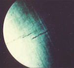
Figure 14. Borescope image of rotor bore indication -
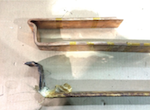
Figure 10. The original, cracked, main lead J-strap is shown in the lower... -
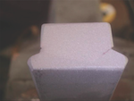
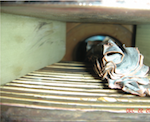
Figure 13. Low cycle fatigue crack in rotor slot wedge. These wedges support... -
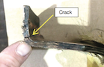
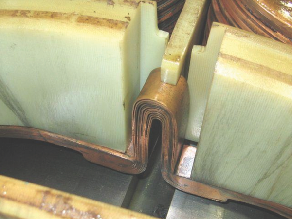
Figure 9. Fatigue cracking found in J-strap lead bend, close to braze... -

Figure 3. Flexible pole crossover in the shape of an omega (O) -
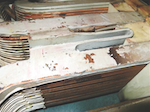
Figure 4. Omega shaped pole-to-pole connector, oriented axially -
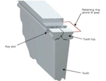
Figure 11. Alternating compressive forces can initiate cracks in rotor tooth... -
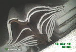
Figure 5. Borescope inspection image showing that even flexible pole-to-pole... -
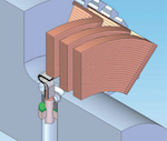
Figure 6. Terminal stud arrangement with both a stiff radial lead component... -
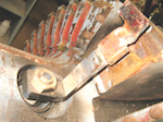
Figure 7. J-strap design consisting of a thick piece of copper (single layer)... -
Figures 8a. Terminal stud failures in the “flexible,” laminated, copper section -
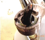
Figures 8b. Terminal stud failures in the “flexible,” laminated, copper section -
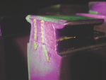
Figure 12. Fluorescent penetrant test shows rotor tooth top crack -
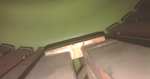
Figure 1. Stiff, T-shaped, pole-to-pole crossover with crack -
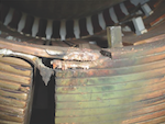
Figure 2. Stiff, single-strap pole-to- pole crossover – open circuit failure

