GAS?TURBINE TECHNOLOGY
MHI sees a future for both steam and all-air cooling
1 July 2009Recently launched gas turbine concepts from MHI include the J-series, a further evolution of its well established steam cooled technology and the M501GAC, a return to all-air cooling.
With over sixty of its G machines (G, G1 and G2) sold since 1997, MHI has a larger fleet of operating steam-cooled gas turbines than any other vendor, and is planning to take the technology to new levels of efficiency with its recently announced J-class gas turbine (see Figure 1 and Modern Power Systems, April 2009, p4). But the company has also recently taken a step in a very different direction, with the launch of a fully air cooled version of the G, the M501GAC – with the aim of responding to user demands for flexibility.
Both the J and the GAC will benefit from some of the technologies being developed as part of the Japanese national project for a 1700°C class gas turbine. This effort, underway since 2004, envisages a combined cycle efficiency of 62-65% (LHV) and requires the use of exhaust gas recirculation to counteract the higher NOx emissions that necessarily arise from such high temperatures (see Figure 2).
Steam cooling experience
The advanced, 1700°C, machine is also expected to employ steam cooling, in which MHI has been something of a pioneer – but it is unlikely to be extended to rotating components. Although around eight years ago MHI completed tests on an H class gas turbine, which had steam cooling of stationary and rotating parts (as in GE’s H) this was never offered commercially – and in its current product range the steam cooling is confined to stationary parts. In the case of the M501G (60 Hz) and M701G (50 Hz) the combustion liners (also known as transition pieces) are steam cooled, while in the newer M501G1 and M701G2 models the steam cooling is extended to the row 1 blade ring and the row 1 and 2 blade rings respectively (all fixed components).
The new J will adopt a similar steam cooling configuration to the G2 (ie combustion liners plus row 1 and 2 blade rings).
The combustion liners need cooling to keep the metal at an acceptable temperature. The aim of steam cooling is twofold: to decrease NOx by reducing the amount of air used for cooling; and to avoid the combustor exit gas temperature drop that arises from air cooling. The steam cooling is closed loop while in the case of air cooling the air mixes with the main gas stream, reducing its temperature. This means that for a given flame temperature (which exponentially determines NOx production) steam cooling of the combustion liners allows a higher turbine inlet temperature to be achieved, which is the key determinant of gas turbine efficiency.
In the case of the G (see Figure 3), the turbine inlet temperature is 1500°C, with a flame temperature of 1500-1600°C, while for an air cooled F class machine the same flame temperature results in a turbine inlet temperature of 1400°C.
The aim of steam cooling the blade rings is to provide active tip clearance control for greater efficiency (see Modern Power Systems, May 2004). The steam has a warming effect during start up and a cooling effect at full load conditions.
The first M501G1 was installed at MHI’s T-Point facility in 2003, while the first M501G1 outside Japan, that at Port Westward (see Modern Power Systems, February 2006), entered commercial operation in 2007.
The first installation to use M701G2 machines, at Tokyo Electric Power’s LNG-fuelled Kawasaki station (see Modern Power Systems, November 2006), was declared fully commercial on 5 February 2009, with a demonstrated efficiency (LHV) of 59.18% (site conditions).
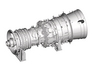
Figure 4 shows the key distinguishing features of the M701G2.
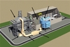
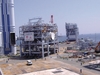
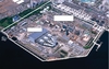
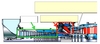
The new Kawasaki facility (Figures 5 and 6) consists of three 500 MW (at 5°C ambient) single-shaft combined cycle blocks, each equipped with an M701G2 gas turbine, HRSG (triple pressure, reheat), steam turbine and generator.
The M701G2, at 334 MW, is said by MHI to be the largest gas turbine currently in commercial operation. (Siemens has reported 340 MWe for its H at Irsching, which it claims as a world record for the unit output of an operating gas turbine. But the Irsching H cannot be considered to be in commercial operation. General Electric’s 9H must also be a contender, however GE does not publicly give a separate rating for its H gas turbine, only the full 9H class combined cycle plant, which is rated at 520 MWe.)
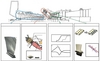
The Kawasaki combined cycle plant has been built on the site of an existing 1050 MWe six-unit conventional gas-fired steam plant, which has supplied power to Tokyo for over 40 years. This was converted from naphtha to LNG in the 1980s and the new combined cycle plant was built in the space formerly occupied by the naphtha tanks. The site is in the heart of Kawasaki, about 20 km from the centre of Tokyo. Vertical-gas-flow HRSGs (manufactured in MHI’s Nagasaki factory) have been used to minimise the plant footprint, along with a very high degree of modularisation to reduce assembly at site. The 3800 t HRSGs were transported from Nagasaki by barge (Figure 7).
Construction of the new combined cycle plant was carried out without interrupting operation of the existing plant and included digging of 65 ft deep tunnels under the old units to accommodate electrical connections to the existing substation.
The second phase of the Kawasaki combined cycle project will consist of replacing the old units (1-6) with a second three-block combined cycle plant, bringing CCGT installed capacity at the site to 3000 MWe.
As well as high efficiency (over 59%, compared with 43% for the old units (LHV basis)) – leading to a big reduction in fuel costs – NOx emissions from the 3000 MWe of CCGT, which is equipped with SCR, will be lower than those for the original plant, despite a tripling of installed capacity. The warm water discharge to Kawasaki Bay will also be greatly reduced, with two thirds of the total power of the new plant coming from gas turbines, greatly reducing the seawater requirements of the steam cycle condensers.
The new combined cycle plants have provision for the supply of steam from the HRSGs to neighbouring industry, allowing the elimination of old and inefficient boilers.
They are also reasonably flexible, with each 500 MWe block at Kawasaki able to go from hot shutdown to full load in 50 minutes from ignition, thanks to an improved hot start-up sequence.
The MHI steam turbines are of the tandem compound double flow exhaust type (TC2F-35.4), with steam conditions of: 12.78 MPa, 564°C (HP); 3.37 MPa, 565°C (IP); and 0.40 MPa, 273°C (LP).
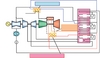
The basic steam flow diagram is shown in Figure 8. IP superheated steam from the HRSG is used for combustor and blade ring cooling. It then joins the hot reheat steam and is fed to the IP turbine, thus effectively recovering exchanged heat from the combustors.
To further enhance overall plant efficiency, boiler feedwater from the HRSG is used for fuel gas heating (FGH) and for cooling of the turbine cooling air (TCA). HP boiler feedwater is extracted from the HP economiser inlet and used for cooling the TCA, while IP feedwater is extracted from the IP economiser outlet and used for the FGH system.
Looking to break the 60% barrier
Not content with the 59% efficiency of the M701G2 in combined cycle mode, MHI is looking to break the 60% efficiency barrier with its steam-cooled J series – due to be commercially available in 2011 – which will have a turbine inlet temperature of 1600°C.
The 60 Hz version of the J (the M501J) will be rated at around 320 MWe (simple cycle) and 460 MWe in combined cycle, the corresponding figures for the 50 Hz version (the M701J) being 460 MWe and 670 MWe) – making it the world’s largest gas turbine by a pretty good margin.
The turbine will be able to withstand temperatures 100°C higher than the 1500°C class G-series thanks to low-thermal-conductivity TBC (thermal barrier coating) and improvements in cooling efficiency, says MHI. Despite the higher temperatures MHI says the NOx emissions from the J are expected to be similar to the G (even without exhaust gas recirculation).
The J compressor, with IGV and three stages of VV, will achieve a higher compression ratio and employ enhanced 3D blade design to improve aerodynamics.
As already noted the J will use some of the core technologies being developed under Japan’s national 1700°C gas turbine programme, in particular the advanced thermal barrier coating.
Return to air cooling
The advanced thermal barrier coating developed under the Japanese national programme will also be among the features to be incorporated in the new all-air-cooled version of the G, the GAC (see Figure 9).
The thinking is that air cooling is simpler than steam cooling and more appropriate for machines operating in a highly cyclic regime (which is roughly the same reasoning that led Siemens to adopt exclusively air cooling for its H class gas turbine).
However, according to a paper by Ai, Koeneke, Arimura and Hyakutake (all of MHI) at Asme Turbo Expo 2009 (Orlando, 8-12 June), this “does not imply MHI’s departure from steam cooling applications.” “The highly reliable and durable steam cooled G engines will continue to be offered and supported” and will be the “backbone of the higher turbine inlet temperature applications currently being evaluated to achieve even higher performance in the near future” (the new J, as discussed above, being an example).
A key challenge presented by the GAC is to maintain the 1500°C turbine inlet temperature, while at the same time minimising the flame temperature and therefore reducing NOx production. The cooling air for the combustor must therefore be minimised, but at the same time the durability of the components must not be compromised. These are the conflicting requirements that have had to be addressed in designing the GAC.
Measures adopted to address these issues include: the improved TBC, with reduced thermal conductivity; more effective use of cooling air; and reduced air leakage.
To reduce NOx generation via improved flame distribution, the GAC also employs MHI’s latest nozzle and swirler technologies (as used in the newest steam cooled G machines): V nozzle (see Figure 10) and improved combustor inlet geometry to improve fuel/air mixing; and modified exit cone and and extended mouth to improve flame holding capability and reduce pilot fuel ratio.
The improved air cooled combustor for the 60 Hz M501GAC has been tested on the HP combustion test rig at Takasago, and been shown to be capable of maintaining 15 ppm NOx at 1500°C turbine inlet temperature, with metal temperatures within allowable limits.
Verification of the M501GAC is expected to be completed this year, prior to commercialisation.
The target power output of the M501GAC is 404 MWe in a 1-on-1 combined cycle application (about 1.3% more than the steam cooled M501G1), while maintaining 15 ppm of NOx.