Instrumentation & Control
Simmering turns up the heat
8 December 2004To help cut costs to meet the demands of a deregulated market Simmering power plant has undergone an extensive control room upgrade that has reduced staffing levels to one operator per unit.
Simmering is an oil/gas-fired combined heat and power plant owned by Wienstrom GmbH. It has an electrical output of 859 MW and up to 630 MW of heat extraction for district heating. It is the largest power station in Austria and comprises two parallel-powered units. Unit 1/2 is rated 433 MWe, 280 MWt, and went into commercial operation in1979. Unit 3/4 is rated at 426 MWe, 350 MWt, and went commercial in 1992.
The primary automation system for the two units was originally a Siemens Teleperm ME process controller, together with an ABB system for the common ancillary systems.
In 1996 each of the two units had its own control room. There was an additional one for ancillary systems. All three control rooms had their own operating staff and were permanently manned. There were also nine local control stations (for the auxiliary steam generators, pump house, screen conveyor building, waste water treatment, pipeline, ammonia storage, limestone unloading, the fuel oil pipeline, for power plant unit 1/2 and for handling duties at the shipping dock) which also had to be temporarily manned on an occasional basis.
Process control for these units demanded a total of eight staff with two more for the ancillary systems. With four shifts to cover 24-hour operation a total of 40 operating staff was needed.
Challenge of deregulation
In 1999, to prepare the plant for the challenges of a deregulated energy market, a comprehensive modernisation project was planned. The aim was to reduce operating costs to meet international yardsticks. It was decided that great savings could be made if each unit shift together with its auxiliary systems could be operated by a single staff member, which was considered feasible if a sufficient degree of automation could be implemented. With a shift supervisor, this would mean a total of only four staff per shift instead of the ten previously required.
Solution
The concept proposed by Siemens included:
- consolidation of the three separate control rooms into a single central control room, to allow staff to stand in for one another on short notice, and to make workable the limitation to a single shift supervisor for the entire plant;
- integration of local control stations into a central control room, to bring control of the remote systems under the hand of control room staff;
- increasing the level of automation – the automation systems now take over most switching actions, reducing the operating load on control room staff;
- improving operation and monitoring of the plant by improving the human/machine interface, standardisating the operating concept, conceiving a layout that was oriented to human factors, and reducing the number of operating elements.
Implementing the plan
As the first step, the automation system for the auxiliary systems was replaced by a Teleperm XP process control system. A conscious decision was made to retain the existing Teleperm ME systems controlling the two power units and to integrate them into the new system environment, mainly to protect the investment already made.
The three systems are now linked via a multimedia-bus (WEB4TXP) and use a Teleperm X operation and monitoring system. The existing control room of unit 3/4 was rebuilt to form the new central control room, equipped with six large-screen displays.
Process optimisation
The relationship among flexibility, efficiency, availability and low emissions is extremely complex. Reduced throttling of turbine valves for example does increase efficiency, but it decreases flexibility as only smaller load change rates are then possible. Nonetheless it is necessary to find a profitable compromise among them. The most profitable operating point differs for each plant and can even vary over time as a function of market requirements. Siemens has developed a range of process engineering software (designated PROFI solutions) to allow a power plant to be operated always at the optimum operating point.
The separate PROFI solutions can be used together. A study is drawn up for each application, during which the optimum combination is determined. The result depends on specific conditions and the goals of the plant owner/operator. Simmering’s aims were to assure its position as a reliable partner for electrical power and district heat generation, and to reduce the workload on control room personnel. These goals demanded fast and repeatable plant startup without manual intervention, improved manoeuverability of plant units and a higher level of automation.
As a result of the specific conditions at this plant – the existing process technology, the stringent requirements imposed for security of supply for district heat – a combination of the following solutions was implemented:
- ‘Low Loss Start’ for cost-optimised startup
- ‘LowStress’ for low-stress plant operation
- ‘FastRamp’ for fast load ramps
- ‘DispatchControl’ for grid-dispatcher control of load changes
- ‘TempOptimiser’ for steam temperature optimisation
Flexibility
The foundation for optimum plant response to load demands while simultaneously ensuring flexible und stable operation was provided at Simmering by control concepts with expansions for lower-level controllers for maximum and minimum load. Provision of additional primary control power (with power demand here derived from grid frequency deviation) and secondary control power (with the load setpoint for the plant set by the grid dispatcher) enables the plant to earn additional revenue. Startup on demand, decreasing minimum load levels or increasing maximum output levels and fast response to changing load requirements reduces financial losses.
Efficiency
Unit efficiency was improved by adopting a number of approaches that included reducing valve throttling losses, and optimisation of combustion air, of steam temperature or of cooling water temperature. This yields increased revenue from power sales at unchanged fuel costs or alternatively reduced fuel costs for unchanged revenue from power sales.
Availability
Implementation of model-based calculation and true feedforward control allows the number of control actions to be kept to an absolute minimum, with the benefits ol reduced wear and tear on control elements, which also reduces load-limiting effects on the associated plant components. Owing to the load capability circuit, loss of major components is ridden out by the plant, with automatic reduction of output to the new maximum level that is permissible without them.
Emissions
Reduction of emissions is achieved by stable plant operation and continuous operating point optimisation for the individual burners. Any increase in efficiency yields a simultaneous reduction in C02 emissions per kWh. This can help a plant avoid paying financial penalties for violation of emissions limits or enable it to generate income by selling superfluous emissions credits. The reduction in unburned carbon content of the ash that results should enable this ash to realise a higher price.
Operational results
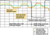
Startup The startup curve for a warm start of unit 3 is shown in Figure 1 . The necessary startup firing rate is calculated from the initial thermal condition of the steam generator prior to firing of the first burner. On increasing the fuel flow, it is necessary to ensure that permitted materials limits are not violated. The required pressure and temperature levels for turbine rolloff are achieved within the shortest possible time. After 70 minutes the generator has been synchronised with the grid and increasing the turbine-generator load starts. Compared to the previous configuration, startup time is reduced by about 30% for each start with associated fuel savings of about 25%, and without any shortening of component life.
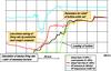
Flexibility A major improvement in the quality of load cycling has been achieved, and the plant now has assured capability for participation in frequency control on the grid. Figure 2 (for unit 1/2) shows that the plant is able to perform major load changes exactly as set, and in either sliding pressure mode or modified sliding pressure mode (actual output, shown green, follows the setpoint, shown in yellow, with very close agreement). On transition from sliding pressure mode to modified sliding pressure mode, the turbine valve is throttled, causing pressure to rise. Steam is then stored in the steam generator and is available for fast load changes for primary control purposes (grid frequency control). Electrical output remains unchanged. The high stability of temperature levels (shown in blue) is evident here, with this applying both for individual load cycles and on transition to modified sliding pressure mode.
Completion
Owners Wienstrom say that the project was completed on schedule and within cost, and that project goals were achieved: the entire power plant with its auxiliary systems can now be operated by a control room staff of only four, including the shift supervisor.
This yielded a number of additional benefits which include:
- cost savings as a result of standardisation of I&C systems for maintenance and spare parts stock, and the centralised engineering of the I&C;
- information availability has improved because inclusion of a multimedia bus enables control room information to be displayed on any PC, allowing networking of the data to the engineering offices in the plant. In fact it is possible to access control room information, using secure private channels on the internet, from a PC anywhere in the world;
- the implementation allows teleservice by the system supplier, who can therefore offer faster troubleshooting services at reduced cost.
Next step
Cost savings by consolidation of separate control rooms, thereby ‘improving the effectiveness of plant personnel’, although an increasing trend is only, in Siemens’ view, a first step . The next, consolidation of the control rooms for the separate plants of an entire power plant fleet, is imminent, and the technology to make it happen already exists.