INSTRUMENTATION AND CONTROL
Turbine start-up at Ringhals 2: hard-wired to software-based
23 June 2004The hard-wired turbine control system of the Ringhals unit 2 reactor, Sweden, is to be replaced with a new software-based system, to be installed in 2006.
Called TA (Turbine Automatic), the new system, which controls turbine plant start-up, monitoring, and shutdown operations, is based on the Westinghouse Supervisory Sequential Controller Interface (SSCI). It is being installed as part of a major instrumentation & control upgrade project underway at Ringhals called TWICE (Ringhals TWo I&C Exchange), which involves modernisation of a major portion of the plant's control, protection and control room systems equipment.
The SSCI is an on-line, workstation-based system designed for operating procedure and sequential control applications in both power plants and process control facilities.
The new TA system at Ringhals 2 gives the plant the necessary commands in the correct order and monitors the plant to ensure that the commands are carried out. The system provides an on-line graphical user interface. This facilitates operator understanding of the evolving plant states resulting from the execution of the TA control sequence and alerts the staff to issues as they arise. It replaces a hard-wired automated system consisting of several electrical equipment cabinets and a "hard" operator interface, with hard push buttons for control and backlit buttons for indication. The SSCI is software based.
The start-up operation consists of 17 steps that involve primary criteria, commands, and secondary criteria. If the primary criteria specified for a step are satisfied, the associated commands are issued. The system then checks that the actions requested by the commands have been implemented. If these secondary criteria are satisfied, the logic proceeds to the next step. Each secondary criterion is assigned a tolerance period, the time in which it must be satisfied. If it is not satisfied during this period, the logic execution stops. The tolerance periods vary from 30 seconds to infinity.
If a dangerous operational condition occurs, the TA system orders a partial or a complete shutdown of the plant. These "return programs" return the turbine to the highest possible safe step of the start-up sequence. Analogous to secondary criteria, return checks ensure that the commands issued by return programs are carried out.
The system can be run in "command" mode or "advisor" mode. In "advisor" mode, the operator must use plant controls to start pumps, fans, etc. Various adjustable (off-line) time delays are used to allow feedback and confirmation from monitored process conditions.
The system also includes a "search" process, whereby synchronisation with the plant occurs. The system finds the highest level from which it is allowed to complete the start-up sequence. When the search sequence is completed, the TA start-up sequence will be placed in the correct step, in manual mode, waiting for the operator to take further action.
Man-machine interface
The TA system's man-machine interface is comprised of an executive interface, a procedure interface, and an overview display.
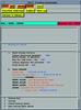
Executive interface screen
The executive interface screen is arranged so that the procedures or sequences are grouped in tree-structured menus. The user may launch any sequence from the executive interface screen. The desired sequence is chosen from the list. The executive interface screen also shows the status of each sequence, including the current mode as well as whether entry conditions are satisfied or not.
From the executive interface screen, the user has global control of all the sequences.
An example of the executive interface screen is shown in the picture above.
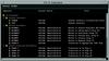
Procedure interface screen
The procedure interface screen is arranged so that the user may ascertain the relevant information about the sequence, including what mode the procedure is in currently, whether it is in manual or automatic control, and what step the sequence is in currently.
Multiple procedure interface screens may be displayed if it is necessary to implement several procedures at the same time.
The illustration below is an example of the procedure interface screen.
The mode selection buttons are "manual/auto" and "command/advisor." "Command" mode means that the procedure is running either under automatic or manual control, with plant process commands being issued. "Advisor" mode means that the procedure is running either under automatic or manual control, with no plant process commands being issued. The sequence may be in an initial, stopped, automatic, manual, violated, or complete mode, where:
• "Initial" indicates that the procedure is ready to be started in either "command" or "advisor" mode and either "manual" or "automatic".
• "Stopped" indicates that the procedure has been stopped by the TA executive or the procedure has been halted by an unsatisfied plant condition.
• "Automatic" indicates that the procedure is progressing through the steps of the sequence without user input until an unsatisfied plant condition is encountered.
• "Manual" indicates that the procedure is being controlled by the user, and therefore not advancing except under explicit user command.
• "Violated" indicates that the procedure was in automatic and the conditions for the current step were not satisfied.
*"Complete" indicates that the procedure has been completed. If the entry conditions continue to be satisfied and the procedure is in automatic, the procedure will restart itself.
To the right of the mode selection buttons is the sequence control button, "reset". The "reset" button allows the user to reinitialise the procedure and start again.
The next section contains the sequence information buttons, with which the user will control what additional information is displayed. The "start/stop conditions" button will display the procedure starting/stopping conditions information. The "graphics" button will allow the user to display an existing graphic that has been associated with the current step in the procedure. Any number of graphic displays may be associated with a step. The "short log" menu button allows the user to display a short version of the log that has been created by the system, which will enable the user to view the pathway that the procedure followed up to the current time.
The next area of the screen is reserved for the user prompts, which will be displayed as they are pertinent for a given procedure step. These prompts will not be used unless the system is in manual. These prompts will, for example, direct the user to the next relevant step in the procedure, allow the user to branch around steps, either forward or backward, and to display alternate conditions of operation, if they exist for that step.
The next space in the procedure interface screen is a message area where information concerning the procedure mode is displayed. To the right of the message area is the timer associated with each step. This shows the user how much time remains until the step is violated.
The remainder of the procedure interface screen is used to display the current procedure. First, the steps that have been implemented are shown in a scrollable area above the currently active step. The status of the step when it was exited is shown, as well as the time at which it was exited. Next, the current procedure step is displayed. The status of the relevant plant components and parameters is displayed. This is an active area, and any changes to the plant, either through operator or plant-induced actions, will be clearly visible in this area, since the plant data are updated. This area is also scrollable, except that the high-level statement representing the purpose of the step is always shown. Also, the upcoming steps are displayed in a scrollable area below the currently active step, allowing the user to view what conditions and/or actions are expected in the future.
In the example shown, "TA21" is the active sequence, and it is being implemented in "manual/command" mode. Step 1 is the current step. This step involves checking the bearing oil system. The primary criteria have been checked in substep a, and they are all satisfied. When the operator leaves substep b, the orders for this step will be given.
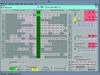
Overview screen
The illustration above represents an example of the overview graphic display that will show the operators the status of progression of the TA system.
The column of green lights labelled 0 to 17 represents the steps of the sequence. As the SSCI system executes the steps, these lights will become active, one at a time, showing the operators the current step of the sequence. When a step is active, it will indicate a shade of green that differentiates the step from the other, inactive steps. During a return, the step that was active when the return was initiated remains lit, until the new target step has been reached. At that time, both the old step and the new step will be lit. The operator will then select the "clear" (kvittering) button (see below) to clear all the lights, after which only the current step will be lit.
The column of section buttons/lights labelled 0 to 5 represents the current operating mode of the sequence; that is, if steps 0 to 9 have been successfully completed, the sequence has achieved "dumpning," which means that steam dump mode has been reached. Essentially, as steps are successively completed, the sequence achieves higher and higher levels of operation, represented by the words to the right of the lights. These items also serve as soft "buttons," through which the operator may select the desired mode. If the sequence is on step 3, in "baxning," and the operator pushes button number 4, the sequence will begin to move toward the mode "magnetisering." The selected section button light flashes (yellow) until the step associated with that section is reached, at which time it stops flashing and remains lit (yellow).
The boxes on the left of the figure contain lights that show the primary criteria that must be satisfied before the sequence will advance from step to step. The criteria in red are parameters that, if not fulfilled, will cause a "return" to a safe mode of operation. The parameters in black, if not fulfilled, will cause the sequence to stop, allowing the operator time to investigate the problem. Any criterion that is not satisfied will cause the appropriate light to activate, giving visual information to the operator that something is wrong. As the primary criteria are satisfied for a step, commands are issued that open valves and start pumps, for example.
An unfulfilled primary criterion will cause SSCI to stop (go into manual) at the relevant step in the TA sequence.
If the primary criterion causes a return, the return program will run. When it is finished, the operator pushes the "clear" button. This will cause any fulfilled primary criteria that were blinking before the return to stop blinking. If a primary criterion is not required after a return, the "clear" button will also cause it to stop blinking.
In addition, pop-up displays for each primary, secondary and return criterion will be created by RAB with the textual information that is desired. These are accessed by pressing the button labelled P1, P2, etc, S1, S2, etc, and R1, R2, etc on the overview display.
The boxes to the right of the figure (1.21, 1.22, etc.) show the secondary criteria that must be satisfied. These criteria represent the parameter and component states that should exist after the completion of the commands issued as a result of the fulfilled primary criteria. However, there is also another element involved here - that of time. Each secondary criterion has a tolerance time within which it must be satisfied; if it is satisfied within that time, the light does not go on. If it is not satisfied within the tolerance time, the light representing the condition blinks, signifying a problem. If the secondary criterion is not fulfilled during the tolerance time, the color of the box is cyan. The unfulfilled SC will cause SSCI to stop (go into manual) at the relevant step in the TA sequence.
The far right of the overview screen includes the "return" sequences that are followed if one of the "red" primary criteria is not satisfied, or if a lower operating mode is selected. These are sequences that help bring the plant back to a stable, safe operating condition. These boxes light as the return sequences are executed. The colour red (steady on) indicates the active return or intermediate step. The modes of the return sequences are also shown.
The lower right of the screen shows the "return criteria," which, like the secondary criteria described above, must be satisfied within a specified period. These criteria are examined during the return sequences. The boxes blink if the item is not fulfilled within the tolerance time, during the period in which the return is being implemented. If the return criterion is not fulfilled during the tolerance time, the colour of the box is cyan.
The control buttons are located along the bottom of the TA display:
• SEARCH (Synkprogram): This button initiates the search, or localisation, process. A confirmation pop-up window requires two actions before the search is initiated. This button is lit while the search is being performed. When the search is completed, the operator pushes the "Clear" button.
• MANUAL/AUTO (Man/Auto): This button allows the operator to place the main sequence in AUTOMATIC mode or MANUAL mode. A confirmation pop-up window requires two actions before the choice of AUTO or MANUAL is initiated.
• ADVISOR/COMMAND (Från/Till): This button allows the operator to place the main sequence in COMMAND mode (issue outputs) or ADVISOR mode (do not issue outputs). A confirmation pop-up window requires two actions before the choice of COMMAND or ADVISOR is initiated.
• CLEAR (Kvittering): This button operates as described above. This applies to any PC, SC, or RC (including return steps, such as R2, Z2, etc), as well as any step light. A confirmation pop-up window requires two actions before the clear is initiated.
In addition to these control buttons, an indication of the main sequence mode is shown along the bottom of the TA overview display, as well as an indication of whether the main sequence is capable of giving out orders or not.
What are the benefits?
The major benefit of the computerisation of the turbine start-up system at the Ringhals plant is enhanced situation assessment by the operator. In addition, the system simultaneously monitors multiple plant parameters, brings all procedural information to one location, and provides detailed record keeping capability of the sequence execution.
In addition to the computerisation of the turbine start-up at Ringhals, emergency operating procedures (EOPs) at the Beznau nuclear plant in Switzerland have been computerised (see Modern Power Systems, April 2002).
A coal-fired power plant in Pennsylvania has used the Westinghouse computerisation system for a start-up procedure and the Temelin nuclear plant in the Czech Republic has computerised a variety of normal operating procedures, including primary side sequences, secondary side sequences and valve testing sequences, and it is in the process of automating the EOPs.